Steering device for engine conveyor line

A steering device and engine technology, applied in the direction of transportation and packaging, conveyor objects, etc., can solve the problems of heavy engine weight, engine bottom wear, offset, etc., achieve high-precision reversing operation, and reduce wear effects

Active Publication Date: 2021-04-02
南京文翔自动化设备有限公司
View PDF10 Cites 0 Cited by
  • Summary
  • Abstract
  • Description
  • Claims
  • Application Information

AI Technical Summary

Problems solved by technology

[0003] The above-mentioned existing technical solutions have the following defects: the existing conveying line is directly designed with a curve, but the overall weight of the engine is large, and slipping and deviation often occur when turning on the conveying line, so the conveying is stable Poor performance and easy to wear on the bottom of the engine

Method used


Image

  • Steering device for engine conveyor line
  • Steering device for engine conveyor line
  • Steering device for engine conveyor line

Examples


Embodiment Construction

[0037] The present invention will be described in further detail below in conjunction with the accompanying drawings.

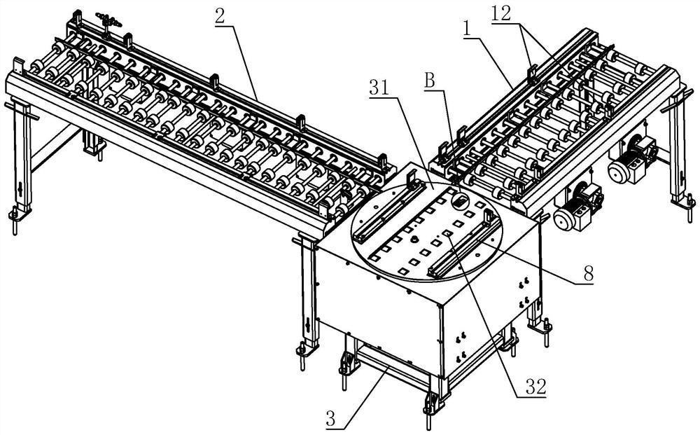
[0038] refer to figure 1 , is a steering device for an engine transmission line disclosed in the present invention, comprising a first transport frame 1 and a second transport frame 2, the first transport frame 1 and the second transport frame 2 are arranged at an angle of 90°, the first transport frame 1 A bogie 3 is arranged between the second conveyor frame 2 .

[0039] refer to figure 1 , the first conveyor frame 1 is provided with an L-shaped first guide plate 11, and when the engine 9 is placed on the first conveyor frame 1, the positioning groove 91 at the bottom of the engine 9 (such as Figure 8 ) cooperates with one side of the first guide plate 11 along the vertical direction, so that when the engine 9 moves on the first transport frame 1, the first guide plate 11 can play a guiding role for the engine 9, reducing the generation of the engine 9 a...


PUM


Abstract

The invention relates to a steering device of an engine conveyor line. The steering device comprises a first conveying frame and a second conveying frame which form an angle. A steering frame is arranged between the first conveying frame and the second conveying frame and provided with a supporting disc. Multiple rolling wheels are arranged on the supporting disc in the same direction. The upper surfaces of the rolling wheels are higher than the supporting disc and abut against the bottom of an engine. A drive mechanism used for driving the rolling wheels to rotate is arranged in the steeringframe. A first motor used for driving the supporting disc to rotate is arranged in the steering frame. The steering device has the effects that a steering action in the conveying process of the enginecan be quickly and conveniently achieved, the engine can be kept still relatively all the time, and the possibility of engine abrasion is reduced.

Description

technical field [0001] The invention relates to the technical field of an engine production line, in particular to a steering device for an engine delivery line. Background technique [0002] At present, during the production process of the engine, the engine needs to be transported. The current method is to directly transport the engine through a whole conveyor belt. However, based on the design requirements of the production workshop, the steering design is usually carried out during the transportation of the engine, thereby saving the production workshop. Space. [0003] The above-mentioned existing technical solutions have the following defects: the existing conveying line is directly designed with a curve, but the overall weight of the engine is large, and slipping and deviation often occur when turning on the conveying line, so the conveying is stable The performance is poor, and it is easy to wear the bottom of the engine. Contents of the invention [0004] In vie...

Claims


Application Information

Patent Timeline
Patent Type & Authority Patents(China)
IPC IPC(8): B65G47/64B65G47/244B65G47/22
CPCB65G47/22B65G47/244B65G47/648
Inventor 尹超胡越叶小雪
Owner 南京文翔自动化设备有限公司
Why Eureka
Try Eureka