Visualized test device and method for calculating width of model pile

A test device and model pile technology, which is applied in the test of foundation structure, construction, foundation structure engineering and other directions, can solve the problems of difficult quantitative research on model pile model pile calculation width, difficult model pile visualization test, etc. Simple disassembly and assembly, convenient installation and fixing effect

Inactive Publication Date: 2020-05-15
SICHUAN UNIV
View PDF3 Cites 1 Cited by
  • Summary
  • Abstract
  • Description
  • Claims
  • Application Information

AI Technical Summary

Problems solved by technology

[0005] The purpose of the present invention is to solve the problem that it is difficult to carry out model pile visualization test based on the similarity principle, and it is difficult to quantitatively study the soil stress diffusion around the model pile and the calculation width of the model pile, and to provide a visual test device and method for the calculation width of the model pile

Method used


Image

  • Visualized test device and method for calculating width of model pile
  • Visualized test device and method for calculating width of model pile
  • Visualized test device and method for calculating width of model pile

Examples


Embodiment 1

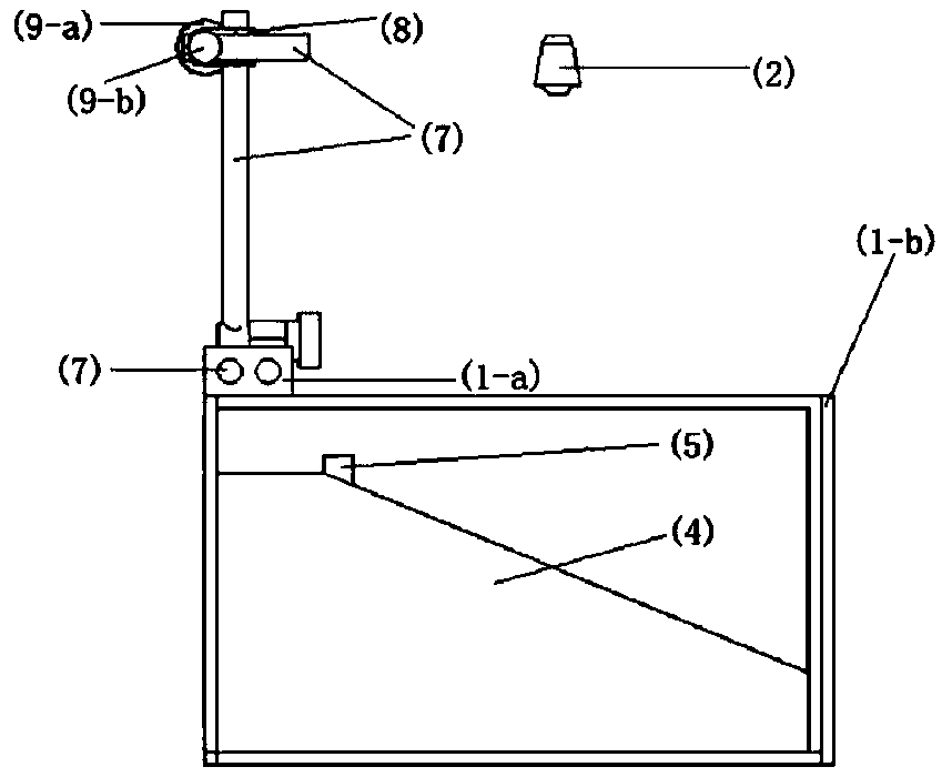
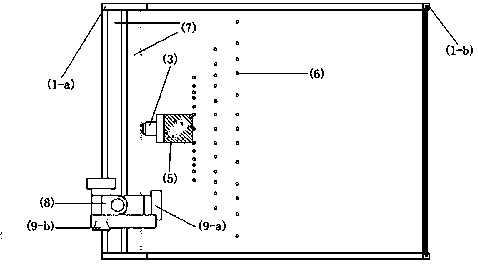
[0045] Such as Figure 1 to Figure 8 Shown is the structural diagram of the visual test device for calculating the width of model piles, including:

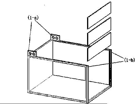
[0046] The visual model box 1 is open at the top, and the filling in the box is model soil 4 configured according to similar principles; the mini scaffold is composed of steel rods 7, bolts 9 and fasteners 8, which are used for lap test equipment; loading device 3 is connected to On the hydraulic servo system, a horizontal load is applied to the exposed part of the model pile 5; the surface of the model soil 4 is symmetrically arranged with displacement points 6 according to the center, 0°, 15°, 30°, 38°, 45° and 52°, press Three rows of piles are arranged at 0.75 times the width of the pile; a high-speed particle camera 2 is installed above the model soil 4, which can be adjusted to clearly capture all displacement punctuation points 6.

[0047] The model box 1 in this embodiment has an inner wall size of 180cm×110cm×150cm (length×wi...

Embodiment 2

[0058] The method of using the visual test device for calculating the width of the model pile described in Example 1 for testing includes the following steps:

[0059] (1) Prepare test materials and equipment

[0060] Measure the physical and mechanical parameters of the prototype soil and the prototype pile, make model soil 4 and model pile 5 with similar physical and mechanical parameters according to similar principles, determine the size of model box 1 according to the size of model pile 5 and boundary effects, prepare displacement punctuation 6, steel rod 7. Fastener 8 and bolt 9, high-speed particle camera 2, loading device 3 and a computer.

[0061] (2) Build a model pile slope model

[0062] The configured model soil 4 is compacted and filled in the model box 1, after filling a certain height, the model piles are buried in the predetermined position, the soil is leveled, and the model soil 4 is continuously compacted and filled until it reaches Predetermine the exposed height...


PUM


Abstract

The invention provides a visualized test device and method for calculating the width of a model pile. The device is mainly composed of a model box, model soil, the model pile, a high-speed particle camera, a bolt, a fastener, a steel rod and displacement marks; and the model box is a transparent box body composed of a steel structure and acrylic, the model soil has similar physical and mechanicalindexes with prototype soil, and the model soil and the model pile are distributed in the model box. The displacement marks are distributed on the surface of the model soil at a certain angle, the bolt and the fastener cooperate with the steel rod to form a mini scaffold used for erecting detection equipment, and the high-speed particle camera is erected right above the model soil body. Compared with an existing test device and test method, overlapping of the visualized test device and method for calculating the width of the model pile is convenient and flexible, stress diffusion of the soil body can be quantitatively analyzed according to a similar principle, the calculated width of the pile body is obtained by calculating, and the visualized test device and method for calculating the width of the model pile can be widely used in the study of pile-soil interaction under different site slopes, soil properties or geometric dimensions of pile bodies.

Description

Technical field [0001] The invention belongs to the technical field of geotechnical engineering and geological engineering, and relates to a model test device and a test method, in particular to a visual test device and a test method for calculating the width of a model pile. Background technique [0002] my country has a vast territory and complex engineering geological conditions. Different site conditions put forward different requirements for the foundations of its structures. Especially in southwest China, slope sites account for about 90% of the land area. In engineering construction fields such as roads, railways, construction, electricity, water conservancy, etc., it is often necessary to set up structures on adjacent slopes or slope sites. Due to the site topography and other reasons, there are many cases of instability of the pile foundation of the slope site due to insufficient horizontal bearing capacity. The design index of its horizontal bearing capacity, such as th...

Claims


Application Information

Patent Timeline
Patent Type & Authority Applications(China)
IPC IPC(8): E02D33/00
CPCE02D33/00
Inventor 康舜刘长武袁勋
Owner SICHUAN UNIV
Why Eureka
Try Eureka