Ignition oil gun head with blockage removal device

The technology of ignition oil gun and oil passage hole is applied in the field of ignition oil gun head, which can solve the problems of low blocking efficiency, long cleaning cycle, complicated operation, etc., and achieve the effects of reducing manpower and material resources, short cleaning cycle and simple operation.

Pending Publication Date: 2020-05-15
内蒙古大唐国际托克托第二发电有限责任公司 +1
View PDF0 Cites 1 Cited by
  • Summary
  • Abstract
  • Description
  • Claims
  • Application Information

AI Technical Summary

Problems solved by technology

[0002] The ignition oil gun is a device that atomizes fuel oil and fully burns the fuel oil through air distribution and ignition. It is often used for ignition and ignition of coal-fired boilers; the oil outlet end of the main body of the ignition oil gun head A splitter and a swirl are arranged in sequence along the oil outlet direction, and the fuel oil with a certain pressure flows into the main body of the gun head through the oil inlet end of the gun body of the ignition gun, and gathers in an annular groove through the small hole of the splitter Then enter the swirl chamber in the center of the swirl through the tangential groove of the swirl plate, and finally generate high-speed swirl motion and spray out from the center hole; because the fuel oil contains oil residue, the ignition oil gun in the actual operation process, The shunt plate in the main body of the gun head is often blocked. In order to ensure that the coal-fired boiler is put into use in time when the operation is unstable, the oil gun must be disassembled and cleaned by the staff in time after the oil gun is blocked, resulting in cumbersome operation and long cleaning cycle. The blocking efficiency is low; and when a large number of ignition guns are blocked, a lot of manpower is required to deal with it, thus, a lot of manpower and material resources are wasted, and the labor intensity of the staff is increased

Method used


Image

  • Ignition oil gun head with blockage removal device
  • Ignition oil gun head with blockage removal device
  • Ignition oil gun head with blockage removal device

Examples


Embodiment Construction

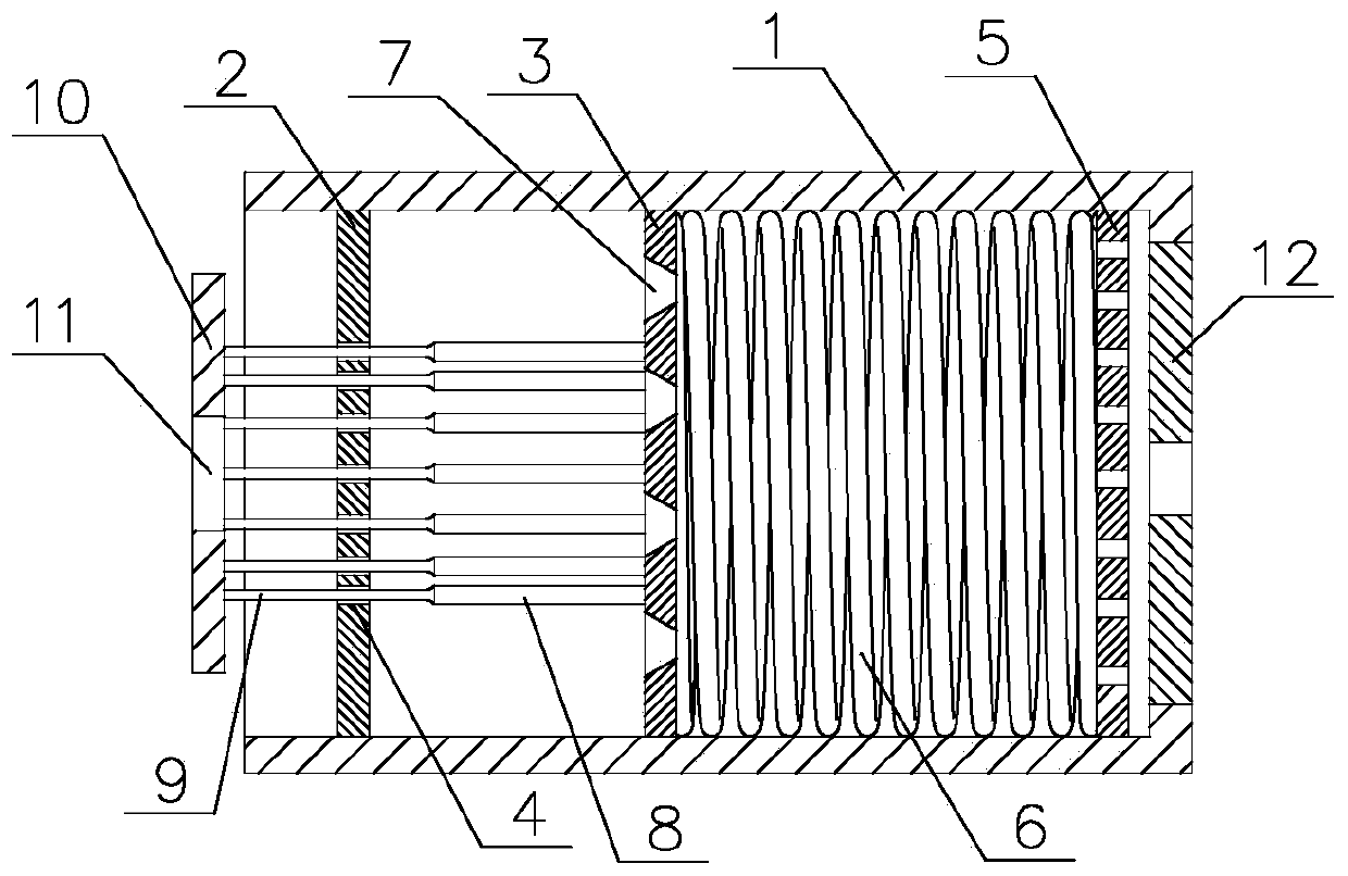
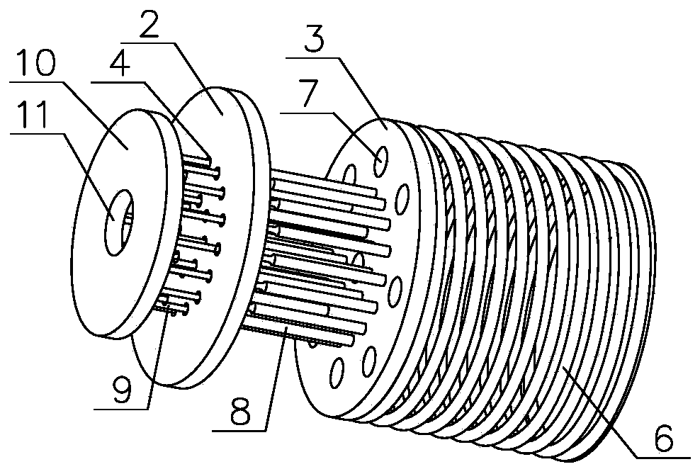
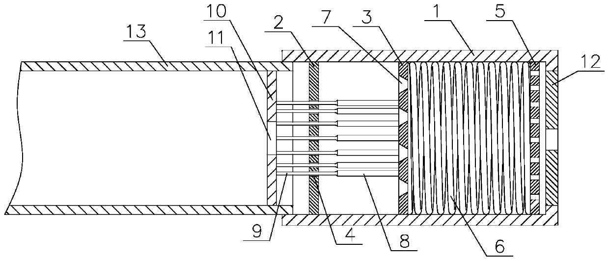
[0011] Such as Figure 1 to Figure 3 As shown, a kind of ignition oil gun head with the plugging device, it comprises gun head main body 1, is fixed with swirl plate 12 on the oil outlet end of gun head main body 1, is fixed in the inner chamber of gun head main body 1 There is a splitter 5 attached to the swirl sheet 12, which also includes a slag cutting disc 2 and a first push plate 3 arranged in the gun head main body 1; The direction from the oil inlet to the diverter plate 5 is provided with a slag cutting plate 2, a first push plate 3 and a spring 6 in sequence; The inner wall of the first push plate 3 is slidingly placed in the inner cavity of the gun head body 1, and the edge of the first push plate 3 is in sliding contact with the inner wall of the gun head body 1; the spring 6 is placed on the first push plate 3 and the shunt 5 Between; on the first push plate 3, there are evenly distributed oil through holes 7, the oil through holes 7 are tapered holes, the open e...


PUM


Abstract

The invention discloses an ignition oil gun head with a blockage removal device. The ignition oil gun head comprises a slag intercepting disc. Slag pushing rods are evenly distributed on the plate surface of a first pushing plate adjacent to the slag intercepting disc. The slag pushing rods slidingly penetrate through oil via holes. The top end of each slag pushing rod is provided with a connecting rod. The ignition oil gun head has the advantages that in the normal operation process, springs are compressed under stress, the connecting rods are placed in the oil via holes of the slag intercepting disc, and fuel oil sequentially passes through the gaps between the oil via holes and the connecting rods and oil passing holes in the first pushing plate, passes through a flow dividing piece anda flow rotating piece and is then sprayed out; when the gaps between the oil via holes and the connecting rods are blocked by the oil slag, a user only needs to stop supplying fuel oil with certain pressure into an ignition oil gun, and at the moment, the springs push the first pushing plate to slide towards the slag intercepting disc; meanwhile, the slag pushing rods are inserted in the oil viaholes and eject out the oil slag, so that the blockage removal function is realized; and the gun head does not need to be detached in the blockage removal mode, operation is simple, the cleaning cycleis short, efficiency is high, and manpower and material resources can be reduced.

Description

Technical field: [0001] The invention relates to the technical field of ignition oil guns for coal-fired boilers, in particular to an ignition oil gun tip with a blockage removal device. Background technique: [0002] The ignition oil gun is a device that atomizes fuel oil and fully burns the fuel oil through air distribution and ignition. It is often used for ignition and ignition of coal-fired boilers; the oil outlet end of the main body of the ignition oil gun head A splitter and a swirl are arranged in sequence along the oil outlet direction, and the fuel oil with a certain pressure flows into the main body of the gun head through the oil inlet end of the gun body of the ignition gun, and gathers in an annular groove through the small hole of the splitter Then enter the swirl chamber in the center of the swirl through the tangential groove of the swirl plate, and finally generate high-speed swirl motion and spray out from the center hole; because the fuel oil contains oi...

Claims


Application Information

Patent Timeline
Patent Type & Authority Applications(China)
IPC IPC(8): F23D11/24F23D11/38
CPCF23D11/24F23D11/386
Inventor 南文乐陈亮亮董成玉
Owner 内蒙古大唐国际托克托第二发电有限责任公司
Why Eureka
Try Eureka