Filtering device and extractor hood with filtering device

A filter device and oil filter technology, which can be applied in application, oil fume removal, household stoves, etc., can solve the problems of difficult cleaning, large filter screen size, and the filtering effect has not been greatly improved, so as to achieve the improvement effect and improve the oil separation. The effect of efficiency

Active Publication Date: 2020-05-15
NINGBO FOTILE KITCHEN WARE CO LTD
View PDF8 Cites 0 Cited by
  • Summary
  • Abstract
  • Description
  • Claims
  • Application Information

AI Technical Summary

Problems solved by technology

[0005] However, the simple superimposition of such planar screens does not greatly improve the filtering effect, and generally the size of the filter screen is large, making it difficult to clean, and the multi-layer oil screen further increases the difficulty of cleaning

Method used


Image

  • Filtering device and extractor hood with filtering device
  • Filtering device and extractor hood with filtering device
  • Filtering device and extractor hood with filtering device

Examples


Embodiment 1

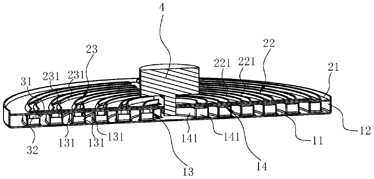
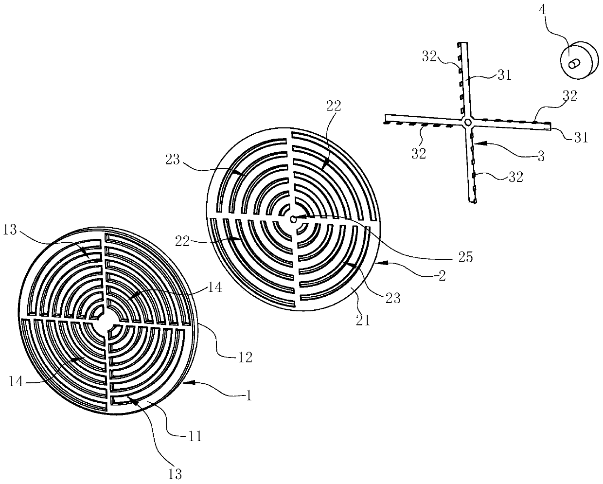
[0036] see Figure 1 ~ Figure 3 , a filtering device, including a first oil filter screen 1, a second oil filter screen 2, an oil screen 3 and a driving mechanism 4. This filter device is mainly used for range hoods.

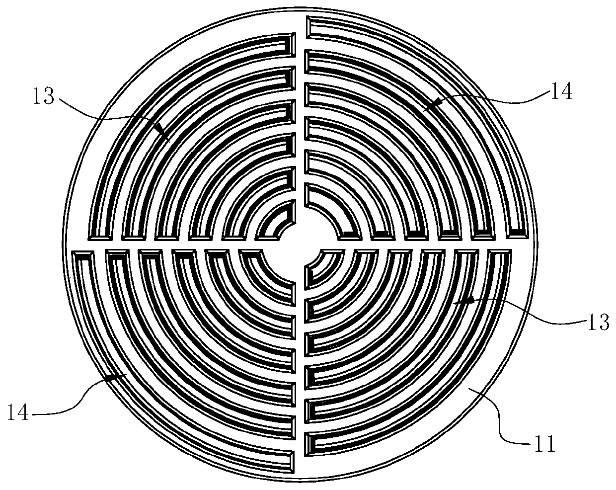
[0037] combine Figure 4 , the first oil filter screen 1 includes a circular first net pan 11 as a whole, a flange 12 bent along the axial direction of the first net pan 11 at the periphery of the first net pan 11, and set on the first net The first air inlet 13 and the second air inlet 14 on the disk 11, and the folded edge 12 are annular. The first air inlet 13 is arc-shaped and has at least two symmetrically arranged relative to the center of the first mesh disk 11 ; the second air inlet 14 is arc-shaped and has at least two symmetrically arranged relative to the center of the first mesh disk 11 . In this embodiment, there are at least four first air inlets 13, at least two on each side of the center of the first grid tray 11, and the first air inlets 13 on ...

Embodiment 2

[0053] see Figure 9 ~ Figure 12 , in this embodiment, the difference from the first embodiment above is that the first air inlet 13 of the first oil filter screen 1 has only one set, and each first air inlet 13 is close to a semicircle, and the second air inlet 14 has only one set, and each second air inlet 14 is close to a semicircle, and there is only one oil guiding groove 15 . Correspondingly, there is only one set of third air inlets 22 of the second oil screen 2, and each third air inlet 22 is close to a semicircle, and there is only one set of fourth air inlets 23, and each fourth air inlet 23 is close to a semicircle, and there is only one connecting rib 24 . The oil screen 3 has only one screen body 31 .

[0054] The working principle of the filtering device of this embodiment is the same as that of the first embodiment.


PUM


Abstract

The invention discloses a filtering device. The filtering device comprises a first oil filtering net and a second oil filtering net. The first oil filtering net comprise a first net disc, and the second oil filtering net comprises a second net disc. First air inlets and second air inlets are formed in the first net disc and are formed in the circumferential direction of the first net disc alternately. The first air inlets and the adjacent second air inlets are formed in the radial direction of the first net disc alternately. Third air inlets and fourth air inlets are formed in the second net disc and are formed in the circumferential direction of the second net disc alternately, and the third air inlets and the adjacent fourth air inlets are formed in the radial direction of the second netdisc alternately. The second oil filtering net can rotate relative to the first oil filtering net, so that the filtering device is opened and closed; when the filtering device is opened, the first air inlets and the second air inlets of the first oil filtering net are opened; and when the filtering device is closed, the second oil filtering net blocks the first air inlets and the second air inlets of the first oil filtering net. The invention further discloses an extractor hood with the filtering device.

Description

technical field [0001] The invention relates to a cooking fume purification device, in particular to a filtering device and a range hood using the filtering device. Background technique [0002] The range hood has become one of the indispensable kitchen appliances in modern families. The range hood works by using the principle of fluid dynamics. Grease particles. The centrifugal fan includes a volute, an impeller installed in the volute and a motor that drives the impeller to rotate. When the impeller rotates, a negative pressure suction is generated in the center of the fan, and the oil fume under the range hood is sucked into the fan, and after being accelerated by the fan, it is collected by the volute and guided out of the room. [0003] At present, the filter screen of the range hood on the market has a poor ability to filter the oil fume. A lot of grease and smoke will eventually accumulate in the impeller and volute of the fan, which affects the service life of the ...

Claims


Application Information

Patent Timeline
Patent Type & Authority Applications(China)
IPC IPC(8): F24C15/20
CPCF24C15/2035
Inventor 刘剑涛
Owner NINGBO FOTILE KITCHEN WARE CO LTD
Why Eureka
Try Eureka