Fluid flow measuring method

A measurement method and fluid flow technology, which is applied to mass flow measurement devices, indirect mass flow meters, etc., can solve the problems of reduced installation space, complicated control process, and large installation space, and achieve reduced installation space, expanded range ratio, and reduced effect of scale

Active Publication Date: 2020-05-15
姜春林
View PDF5 Cites 8 Cited by
  • Summary
  • Abstract
  • Description
  • Claims
  • Application Information

AI Technical Summary

Problems solved by technology

[0005] The invention provides a method for measuring fluid flow, which is used to overcome the defects of high cost, complicated control process, and large installation space in the prior art, and improves the range ratio of flow measurement by changing the cross-sectional area o

Method used


Image

  • Fluid flow measuring method
  • Fluid flow measuring method
  • Fluid flow measuring method

Examples


Embodiment 1

[0027] As shown in accompanying drawings 1-4, an embodiment of the present invention provides a fluid flow measurement method, including the following steps:

[0028] Step S1, collecting parameter signals of the fluid to be measured and obtaining flow rate data;

[0029] Here are three specific ways to obtain the flow rate of the fluid to be measured:

specific Embodiment approach 1

[0030] Embodiment 1: By collecting the pressure difference of the fluid to be measured flowing through the measurement section, the flow velocity is obtained through calculation.

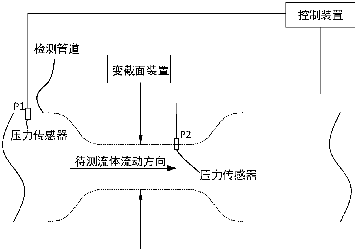
[0031] see Figure 1a , usually through two pressure sensors (the measuring ends are respectively installed at the variable section of the detection pipeline to measure P2 and the inlet end of the detection pipeline P1) or differential pressure sensors (the two measuring ends are respectively installed at the variable section of the detection pipeline and the inlet end of the detection pipeline ) can obtain the pressure difference signal inside the fluid to be tested, where the pressure difference signal is usually an electrical signal, such as a voltage signal or a current signal, and the pressure difference at both ends of the fluid flowing through the pipeline detection section can be obtained through the conversion relationship between electricity and pressure. The above-mentioned conversion calc...

specific Embodiment approach 2

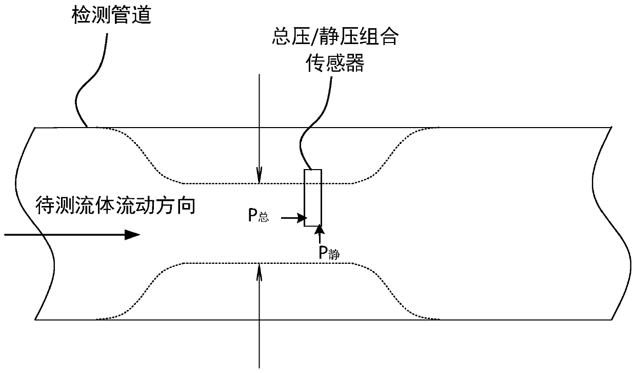
[0036] Specific implementation mode two, see Figure 1b , by collecting the total pressure P of the fluid to be measured 总 and static pressure P 静 , get pressure difference Δp”=P 总 -P 静 , and then calculate the flow rate by differential pressure.

[0037] The total pressure / static pressure combination sensor is installed radially in the variable cross-section pipeline, and the position of the pressure measurement point in the pipeline changes with the variable cross-section parameters, which can be corrected by the fluid velocity distribution of the flow channel cross-section. The difference between the total pressure and the static pressure is the differential pressure, and the flow velocity v is obtained:

[0038]

[0039] In formula (2): Δp”=P 总 -P 静 , ρ is fluid density;

[0040] This method is also applicable to the situation where the axial length of the pipe is shorter in variable cross-section.


PUM


Abstract

The invention discloses a fluid flow measuring method. The method comprises the following steps of collecting parameter signals of fluid to be measured, and obtaining flow velocity data; acquiring a variable cross-section signal of a pipeline through which the to-be-measured fluid flows, and acquiring variable cross-section data; obtaining the area of a variable cross section according to the variable cross section data and original cross section parameters of the pipeline; and obtaining the volume flow of the fluid according to the flow velocity of the fluid and the area of the variable cross-section, or obtaining the mass flow by combining the density of the to-be-measured fluid. By using the method, the problems of high cost, complex control system, large occupied space and the like inthe prior art are solved, the measuring range ratio is increased, measuring pipelines and sensors are reduced, the cost, the control system and the occupied space are reduced, and the maintenance costis reduced.

Description

technical field [0001] The invention relates to the field of flow measurement, in particular to a method for measuring fluid flow by changing the cross-sectional area of ​​a fluid pipeline during the measurement process to improve the range ratio of measurement. Background technique [0002] For the flow measurement of liquid and gas, install the sensor on the pipeline through which the fluid flows, and measure the electrical signal through the sensor. The electrical signal can reflect the pressure difference of the fluid flow inside the pipeline, and the flow velocity of the fluid can be calculated through the pressure difference. According to The relationship between fluid density ρ, flow velocity v, cross-section A and flow Q is: Q=ρ×v×A can obtain mass flow or volume flow Q=v×A; due to the limitation of sensor measurement range, the pressure difference that can be sensed Δp in Δp min ~Δp max Between, for the same measuring pipe, the flow turndown ratio: [0003] ...

Claims


Application Information

Patent Timeline
IPC IPC(8): G01F1/88
CPCG01F1/88
Inventor 吴宇清姜春林
Owner 姜春林
Why Eureka
Try Eureka