Dynamic knee point detection circuit

A technology for detecting circuit and knee point voltage, which is applied in the direction of measuring electricity, measuring electrical variables, measuring current/voltage, etc., can solve problems such as prone to false triggering and large sampling error, and achieve the effect of ensuring sampling accuracy

Active Publication Date: 2020-05-15
UNIV OF ELECTRONIC SCI & TECH OF CHINA
View PDF11 Cites 5 Cited by
  • Summary
  • Abstract
  • Description
  • Claims
  • Application Information

AI Technical Summary

Problems solved by technology

[0005] Aiming at the problems of large sampling errors and false triggers that exist in the above-mentioned traditional knee point detection method, the present invention proposes a dynamic knee point detection circuit, which adopts a ripple amplification and comparison method to compare the feedback voltage VS waveform after ripple amplification, The moment before the knee point and the moment when the knee point is approaching can be distinguished through the change of the ripple, and accurate sampling of the knee point voltage information under different peripheral application conditions can be realized

Method used


Image

  • Dynamic knee point detection circuit
  • Dynamic knee point detection circuit
  • Dynamic knee point detection circuit

Examples


Embodiment Construction

[0028] The present invention will be further described below in conjunction with the drawings and specific embodiments:

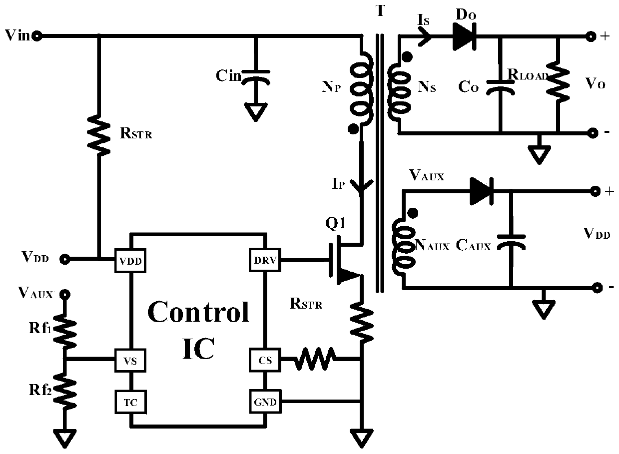
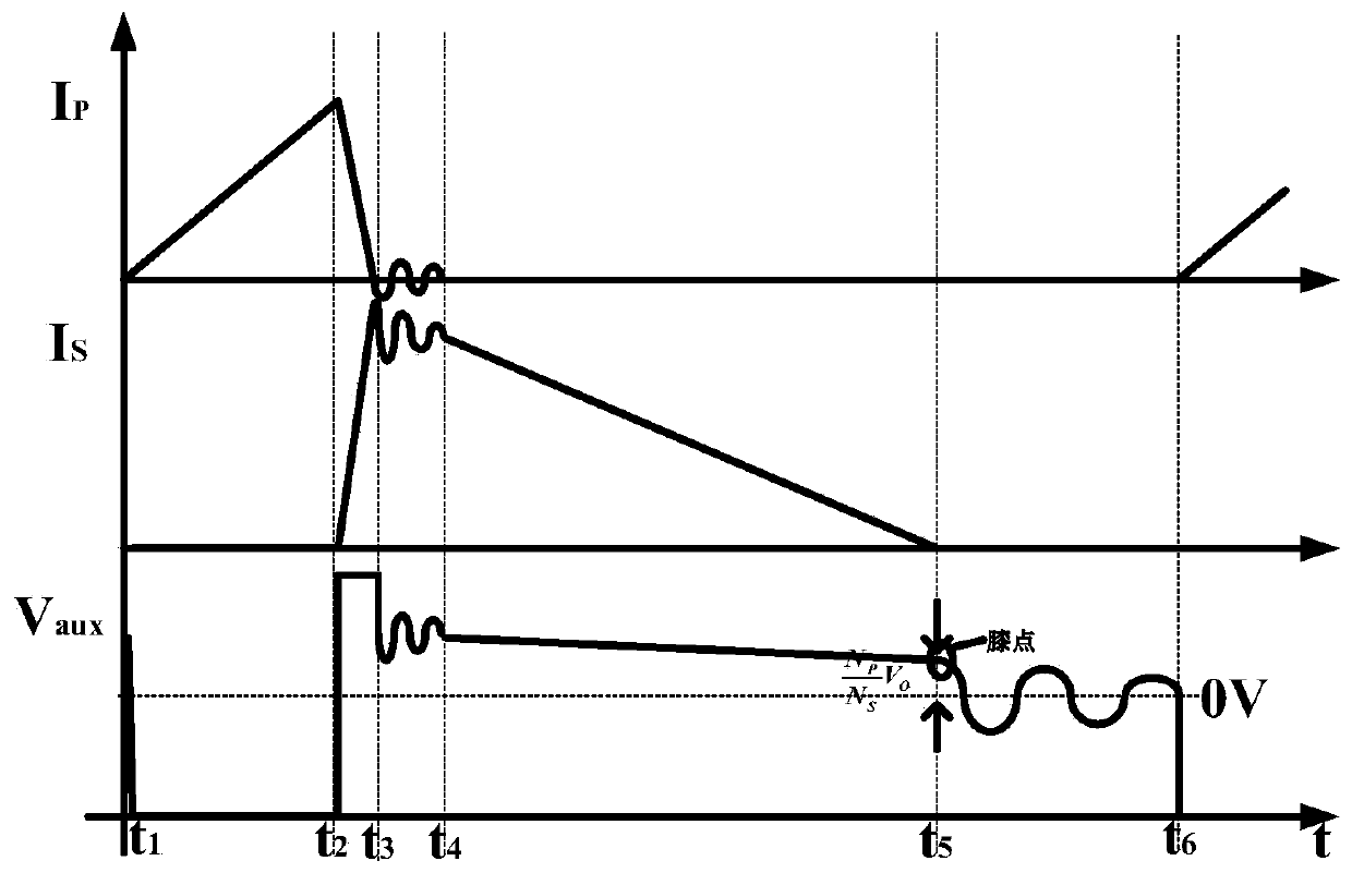
[0029] The dynamic knee point detection circuit proposed by the present invention can be applied to the primary side feedback flyback converter and the secondary side feedback flyback converter. The following is an example of applying the present invention to the primary side feedback flyback converter, such as figure 1 Shown is a schematic diagram of a primary side feedback flyback converter, where I P Current on the main side power tube, I s Is the secondary current, V AUX Is the voltage at the end of the same name on the auxiliary winding, V DD Is the output voltage on the auxiliary winding side capacitor. Such as figure 2 Shown are the waveform diagrams of some key nodes when the primary-side feedback flyback converter is in the discontinuous working mode. 1 -t 2 When the main side is on, the main side power tube current I P Linear rise, the secondary cur...


PUM


Abstract

A dynamic knee point detection circuit comprises a first feedback resistor, a second feedback resistor, a leakage inductance leading edge blanking module, a ripple amplification module, a first comparator, a second comparator, an NOR gate and a dynamic leading edge blanking module, and the first feedback resistor and the second feedback resistor are used for obtaining feedback voltage of voltage of dotted terminals on an auxiliary winding in a flyback converter. The leakage inductance leading edge blanking module is used for shielding the feedback voltage when the secondary side of the flybackconverter just starts to be conducted to generate resonance. The ripple amplification module is used for amplifying the feedback voltage within a transmission band range and then outputting the feedback voltage. The first comparator, the second comparator and the NOR gate are used for judging whether the feedback voltage exceeds a set threshold value or not. The dynamic leading edge blanking module is used for obtaining the arrival time of the knee point voltage and the knee point voltage value. The circuit is suitable for the resonant frequency in a wider range, has higher sampling precision, and cannot generate the problems of false triggering and the like.

Description

Technical field [0001] The invention belongs to the technical field of analog integrated circuits, and relates to a dynamic knee point detection circuit, which can be applied to a flyback converter. Background technique [0002] The growing consumer electronics market has promoted the rapid development of power management technology represented by switching power supplies. In the switching power supply circuit, because the flyback converter has the advantages of simple structure, good electrical isolation between input and output voltage, and does not require output filter inductors, it is the most commonly used topology for low-power power adapters. According to the feedback mode of the output voltage, the flyback converter has primary-side feedback and secondary-side feedback. The secondary side feedback flyback converter uses optocoupler components to directly sample the output voltage information of the secondary side. Although the sampling accuracy is relatively high, the a...

Claims


Application Information

Patent Timeline
IPC IPC(8): G01R19/165G01R1/30
CPCG01R1/30G01R19/16576
Inventor 周泽坤肖志平王佳妮王卓张波
Owner UNIV OF ELECTRONIC SCI & TECH OF CHINA
Why Eureka
Try Eureka