
A polarization multiplexing device for projection system

A polarization multiplexing and projection system technology, applied in the field of optical projection, can solve the problems of reducing the brightness of the projection system, the manufacturing process cannot reach the small size level, and it is extremely difficult to apply.

Active Publication Date: 2020-05-15
SUNNY OPTICAL ZHEJIANG RES INST CO LTD
View PDF7 Cites 1 Cited by
  • Summary
  • Abstract
  • Description
  • Claims
  • Application Information

AI Technical Summary

Problems solved by technology

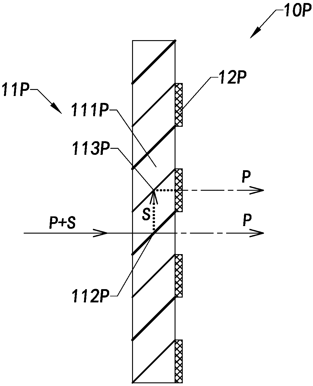
Once there is a deviation between the 1 / 2 wave plate and the output polarized area of ​​the polarized beam splitting array 11P, the purity of the polarized light emitted from the polarization multiplexing device 10P will be reduced, and the brightness of the projection system will be reduced, thereby affecting The image quality of the projection system
[0005] In addition, for the structure of the existing polarization multiplexing device 10P, the current manufacturing process cannot reach the small size level, and cannot meet the small volume development requirements of the current micro-miniature micro-projection system, and it is extremely difficult to apply to today's hot development of augmented reality ( Augmented reality, AR), near-eye display (Near-eye display, NED), wearable and other fields

Method used


Image

  • A polarization multiplexing device for projection system
  • A polarization multiplexing device for projection system
  • A polarization multiplexing device for projection system

Examples


Embodiment Construction

[0053] The following description serves to disclose the present invention to enable those skilled in the art to carry out the present invention. The preferred embodiments described below are only examples, and those skilled in the art can devise other obvious variations. The basic principles of the present invention defined in the following description can be applied to other embodiments, variations, improvements, equivalents and other technical solutions without departing from the spirit and scope of the present invention.

[0054] Those skilled in the art should understand that in the disclosure of the present invention, the terms "vertical", "transverse", "upper", "lower", "front", "rear", "left", "right", " The orientation or positional relationship indicated by "vertical", "horizontal", "top", "bottom", "inner", "outer", etc. is based on the orientation or positional relationship shown in the drawings, which are only for the convenience of describing the present invention...


PUM

PropertyMeasurementUnit
Angleaaaaaaaaaa

Abstract

A polarization multiplexing device for a projection system is used for converting non-polarized light into polarized light with the same polarization state. The polarization multiplexing device comprises a group of polarization multiplexing units. All the polarization multiplexing units are arranged in an end-to-end mode, and each polarization multiplexing unit is provided with an incident plane and an emergent plane opposite to the incident plane and comprises a light conversion element, a light beam splitting assembly and a light reflection assembly. The light conversion element is used forconverting the first polarized light into second polarized light. The light beam splitting assembly is located at one side of the light conversion element and is used for separating the non-polarizedlight incident from the incident surface into second polarized light emitted from the emergent surface and first polarized light emitted to the light conversion element. The light reflection assemblyis located on the other side of the light conversion element and used for reflecting the second polarized light converted by the light conversion element so that the second polarized light can be emitted out from the emergent face.

Description

technical field [0001] The invention relates to the technical field of optical projection, in particular to a polarization multiplexing device used in a projection system. Background technique [0002] In projection systems based on liquid crystal displays such as LCOS and HTPS, in order to meet their polarized lighting conditions, polarizing devices are usually used in the projection system to convert the non-polarized light emitted by the light source system into polarized light. However, during the process of polarized light conversion, the projection system will lose at least half of the light energy, which will undoubtedly reduce the light energy utilization rate of the projection system, and even fail to meet the imaging requirements of high brightness and low power consumption of the projection system. Therefore, in order to improve the light energy utilization rate of the projection system, a polarization multiplexing device is usually used to convert the unpolarized...

Claims


Application Information

Patent Timeline
IPC IPC(8): G02B27/28G03B21/20
CPCG02B27/283G02B27/286G03B21/2073
Inventor 郑光郝希应陈杭陈远胡增新
Owner SUNNY OPTICAL ZHEJIANG RES INST CO LTD
Learn More