Method for improving PVT calculation speed of Beidou II satellite receiver
A technology for satellite receivers and calculation speed, applied in satellite radio beacon positioning systems, complex mathematical operations, instruments, etc., can solve the problems of increasing system loss, reducing system performance indicators, increasing hardware costs, etc., to improve calculation speed, Save system overhead and improve the effect of processing
- Summary
- Abstract
- Description
- Claims
- Application Information
AI Technical Summary
Problems solved by technology
Method used
Image

Examples
Embodiment Construction
[0018] Below in conjunction with accompanying drawing, the present invention is described in further detail:
[0019] In this embodiment, in order to ensure smooth PVT calculation, it is necessary to first determine that the current BDS-2 receiver is in a normal PVT calculation state, that is, the BDS-2 receiver can continuously and stably output local PVT calculation results. After confirming that the receiver is in the normal PVT calculation state, perform PVT calculation.
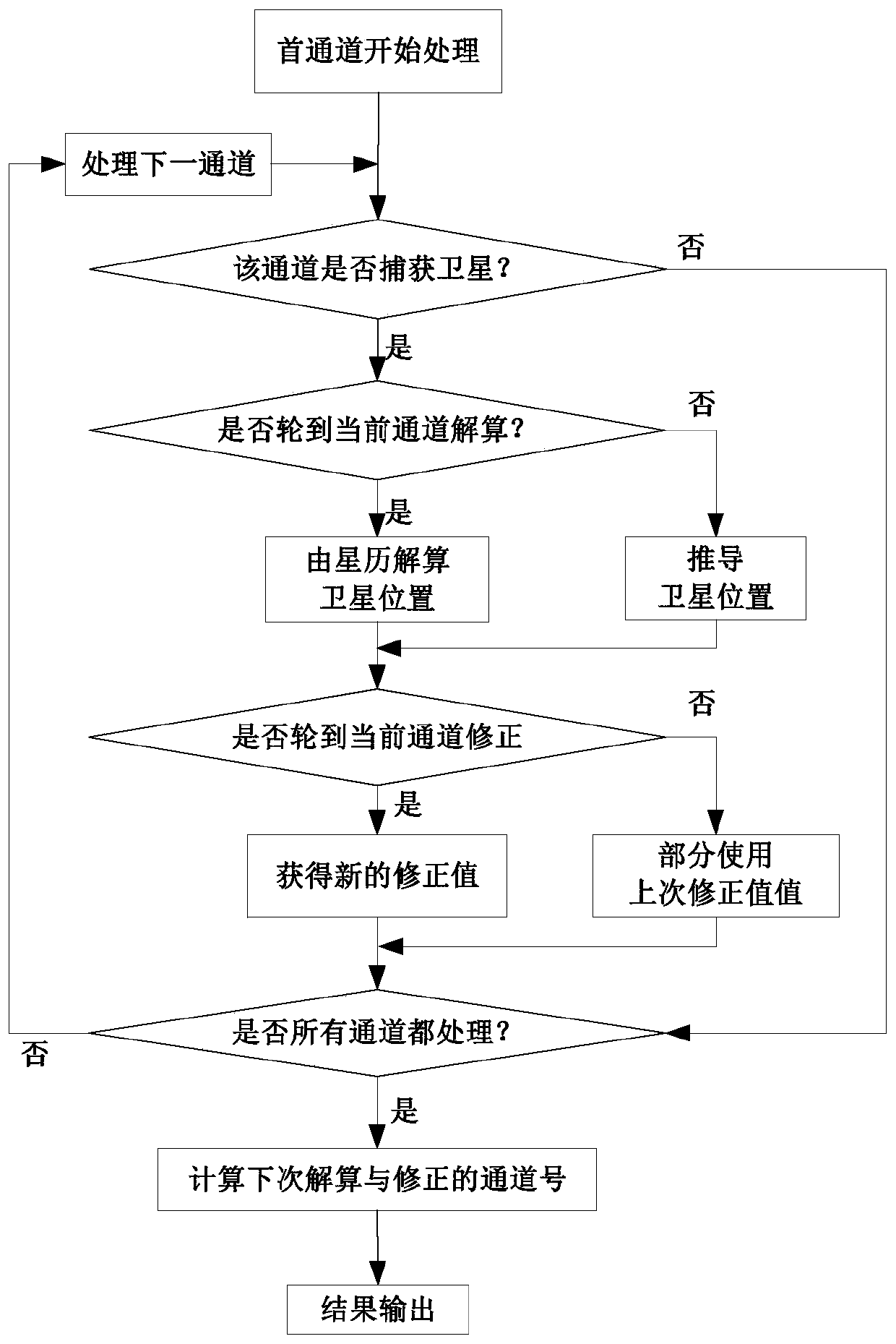
[0020] Such as figure 1 , the specific process of the method for improving the PVT calculation speed of the Beidou No. 2 satellite navigation receiver of the present embodiment includes:
[0021] Step 1: Sort the satellites and traverse the satellites in order, and execute steps (1) to (3) for each satellite traversed. Wherein, sorting the satellites includes sorting according to the satellite acquisition channel number of the receiver. For example, the sequence number of the satellite captured by cha...
PUM
 Abstract
Description
Claims
Application Information
PatSnap Eureka turns technology decisions into work you can execute. Powered by our Innovation Knowledge Graph, it runs expert workflows across engineering, life sciences, materials and intellectual property. Get your review-ready output in minutes.


