
Coil electronic component

A technology of electronic components and coils, applied in electrical components, transformer/inductor coils/windings/connections, transformer/inductor components, etc., can solve problems such as the limitation of the main body strength of inductors

Pending Publication Date: 2020-05-15
SAMSUNG ELECTRO MECHANICS CO LTD
View PDF1 Cites 1 Cited by
  • Summary
  • Abstract
  • Description
  • Claims
  • Application Information

AI Technical Summary

Problems solved by technology

However, there may be limitations in increasing the content of magnetic materials due to the strength of the inductor body, changes in frequency characteristics due to insulation characteristics, and other reasons

Method used


Image

  • Coil electronic component
  • Coil electronic component
  • Coil electronic component

Examples


Embodiment Construction

[0035] Hereinafter, embodiments of the present disclosure will be described as follows with reference to the accompanying drawings.

[0036] However, this disclosure may be illustrated in many different forms and should not be construed as limited to the specific embodiments set forth herein. Rather, these embodiments are provided so that this disclosure will be thorough and complete, and will fully convey the scope of the disclosure to those skilled in the art. Therefore, shapes and sizes of elements in the drawings may be exaggerated for clearer description. In addition, elements having the same function within the scope of the same idea represented in the drawings of each exemplary embodiment will be described with the same reference numerals.

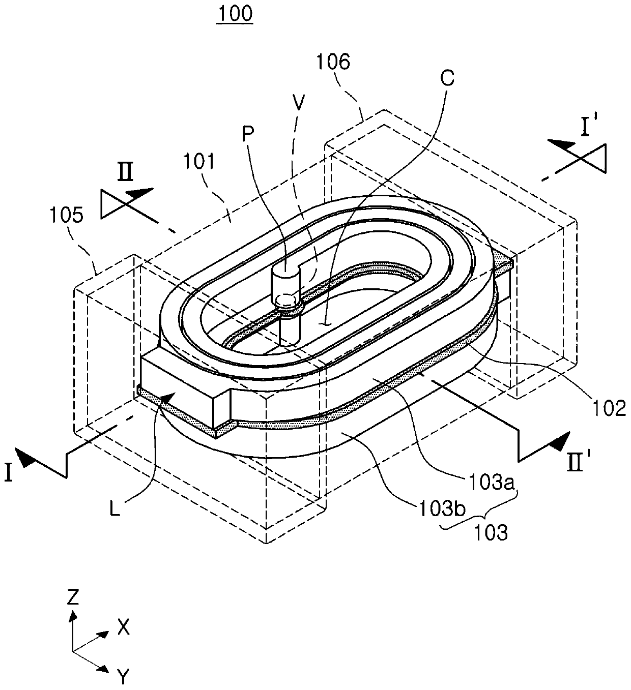
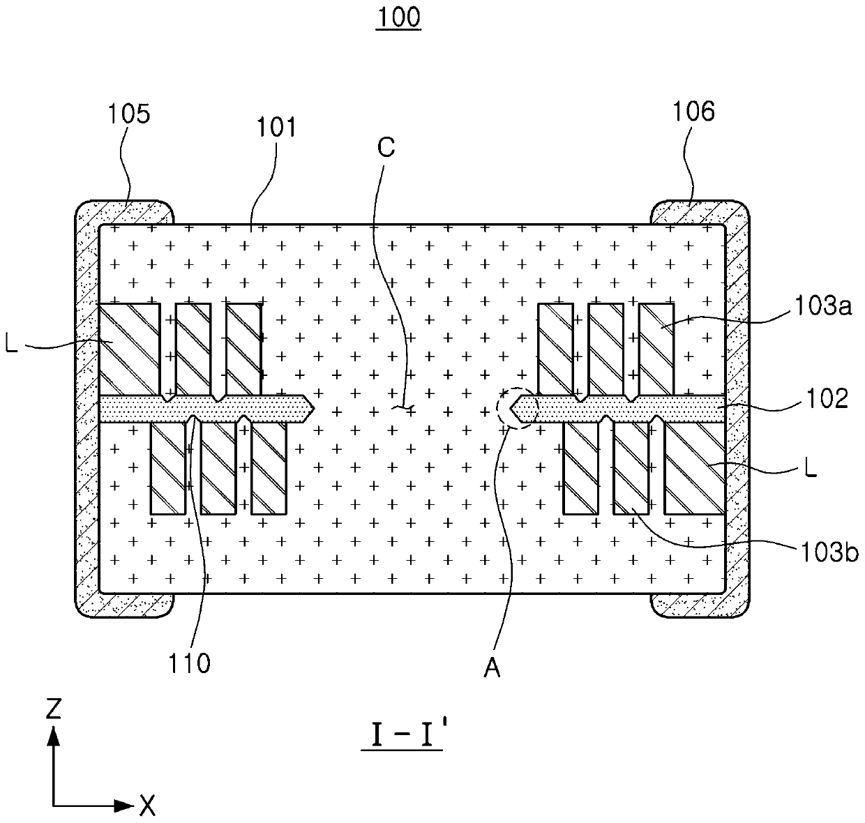
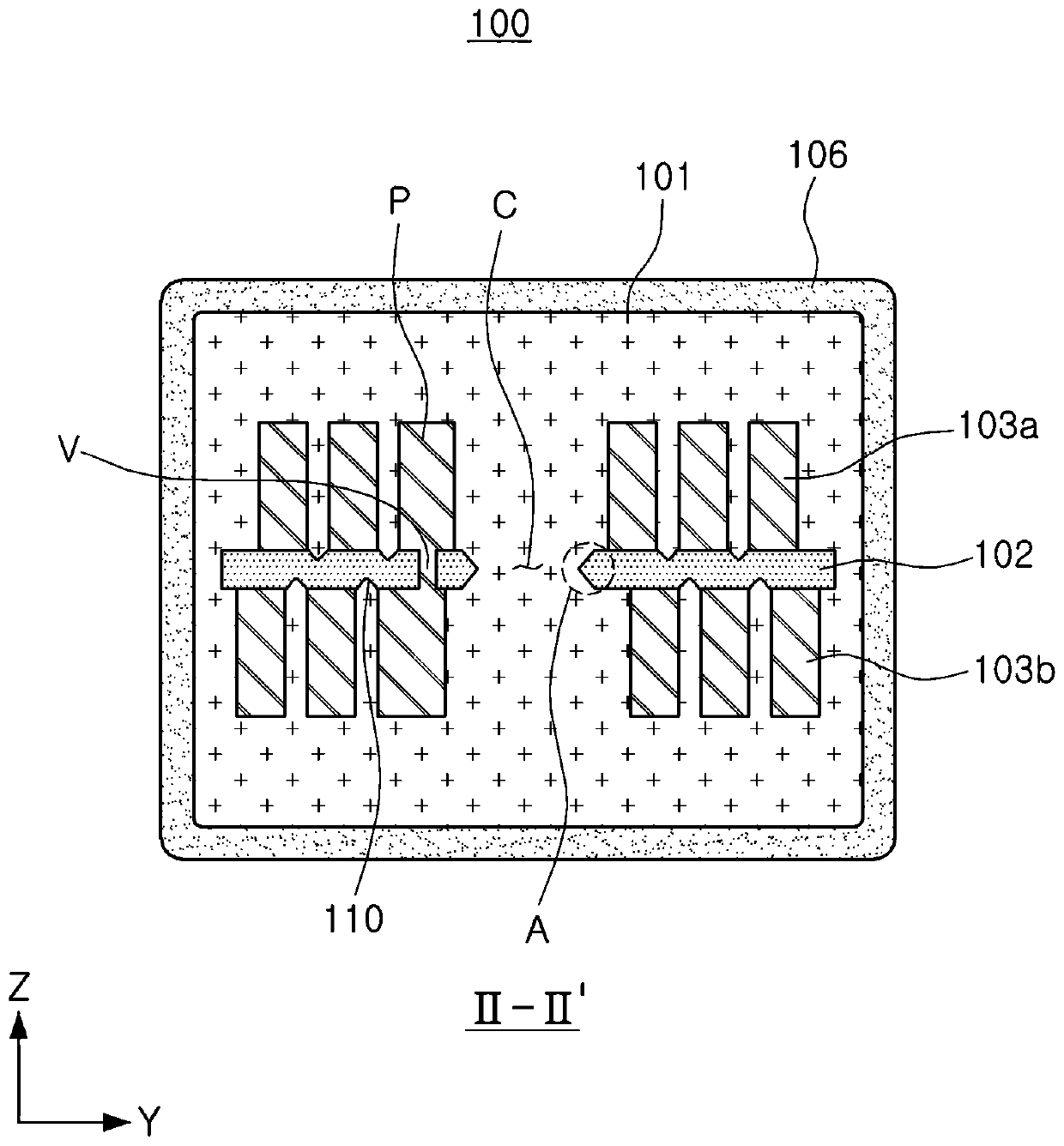
[0037] figure 1 is a perspective view illustrating a coil electronics assembly according to an example embodiment. figure 2 and image 3 are along figure 1 Cross-sectional views taken along line I-I' and line II-II' in . Fig...


PUM


Abstract

A coil electronic component includes a support substrate having a through-hole. First and second coil patterns are disposed on a first surface and a second surface of the support substrate opposing each other, respectively, and each surround the through-hole and are coiled. An encapsulant encapsulates at least portions of the support substrate and the first and second coil patterns, and external electrodes are disposed externally of the encapsulant and are each connected to a respective lead-out pattern connected to a respective one of the first and second coil patterns. A groove penetrates the first surface of the support substrate in a region of the first surface in which the first coil pattern is not disposed, and the second coil pattern is disposed in a region of the second surface ofthe support substrate that overlaps along a thickness direction with the groove penetrating the first surface.

Description

[0001] This application claims the benefit of priority from Korean Patent Application No. 10-2018-0135730 filed in the Korean Intellectual Property Office on November 7, 2018, the disclosure of which is hereby incorporated by reference in its entirety. technical field [0002] The present disclosure relates to a coil electronic assembly. Background technique [0003] As electronic devices such as digital televisions, mobile phones, laptop computers, etc. have been designed to have a reduced size, the demand for coil electronic components configured to be used in such electronic devices and to have a reduced size has been improve. In order to meet such demands, much research has been conducted to develop various types of coil-type or thin-film-type coil electronic components. [0004] One of the major difficulties in developing coil electronics with reduced dimensions is to provide coil electronics with the same characteristics after reducing the size of the coil electronics...

Claims


Application Information

Patent Timeline
Patent Type & Authority Applications(China)
IPC IPC(8): H01F27/28H01F27/29H01F27/32
CPCH01F27/2804H01F27/327H01F27/292H01F2027/2809H01F17/0013H01F2017/0073H01F2017/048H01F17/04H01F17/0006H01F2017/002H01F27/29H01F41/041H01F27/323
Inventor 朴广一李宗珉
Owner SAMSUNG ELECTRO MECHANICS CO LTD
Learn More