air conditioner
A technology for air conditioning and control devices, applied in air conditioning systems, high-efficiency conditioning technology, climate sustainability, etc., can solve problems such as the decrease in refrigerant leakage rate, and achieve the effect of reducing refrigerant leakage
- Summary
- Abstract
- Description
- Claims
- Application Information
AI Technical Summary
Problems solved by technology
Method used
Image

Examples
Embodiment approach 1
[0028] [air conditioner]
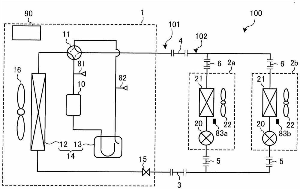
[0029] figure 1 It is a figure which schematically shows an example of the circuit structure of the air-conditioning apparatus concerning Embodiment 1 of this invention. In Embodiment 1, the air conditioner 100 has a refrigerant circuit 101 that connects the outdoor unit 1 and the two indoor units 2a and 2b by using the liquid main pipe 3, the gas main pipe 4, the liquid branch pipe 5, and the gas branch pipe 6. connected to form. In addition, the air conditioner 100 includes a control device 90 , and performs normal operations such as cooling operation mode and heating operation mode, leakage reduction operation, and the like.
[0030] Each liquid branch pipe 5 connects the liquid main pipe 3 to each indoor unit 2a, 2b, and each gas branch pipe 6 connects the gas main pipe 4 to each indoor unit 2a, 2b. Hereinafter, in the refrigerant circuit 101, the circuit of the outdoor unit 1 is referred to as a heat source side circuit, and the liquid main p...
Embodiment approach 2
[0108] Figure 10 It is a figure which schematically shows an example of the circuit structure of the air-conditioning apparatus concerning Embodiment 2 of this invention. In addition, in Figure 10 In the air-conditioning device 200, the pair has the same figure 1 Portions with the same configuration in the air-conditioning apparatus 100 are denoted by the same reference numerals, and description thereof will be omitted. The configuration of the outdoor unit 1 of the air-conditioning apparatus 200 according to the second embodiment is different from that of the first embodiment. In Embodiment 2, the outdoor unit 1 includes the check valve 17 in the piping 103 between the flow path switching device 11 and the accumulator 13 .
[0109] The outflow suppression operation in Embodiment 2 will be described. In addition, the refrigerant recovery operation and the refrigerant transfer operation in the second embodiment are the same as those in the first embodiment.
[0110] [Out...
Embodiment approach 3
[0116] Figure 11 It is a figure which schematically shows an example of the circuit structure of the air-conditioning apparatus concerning Embodiment 3 of this invention. In addition, in Figure 11 In the air conditioning unit 300, the pair has the same figure 1 Portions with the same configuration in the air-conditioning apparatus 100 are denoted by the same reference numerals, and description thereof will be omitted. The configuration of the outdoor unit 1 of the air-conditioning apparatus 300 according to the third embodiment is different from that of the first embodiment. In Embodiment 3, the outdoor unit 1 is provided with the second shutoff device 18 a in the piping 104 between the gas main pipe 4 and the flow switching device 11 .
[0117] The outflow suppression operation of Embodiment 3 will be described. In addition, the refrigerant recovery operation and the refrigerant transfer operation in the third embodiment are the same as those in the first embodiment.
...
PUM
 Abstract
Description
Claims
Application Information
 - R&D
- Intellectual Property
- Life Sciences
- Materials
- Tech Scout
- Unparalleled Data Quality
- Higher Quality Content
- 60% Fewer Hallucinations
Browse by: Latest US Patents, China's latest patents, Technical Efficacy Thesaurus, Application Domain, Technology Topic, Popular Technical Reports.
© 2025 PatSnap. All rights reserved.Legal|Privacy policy|Modern Slavery Act Transparency Statement|Sitemap|About US| Contact US: help@patsnap.com