

Electromagnetic-multipoint composite forming device and forming method for sheet material
A composite forming and plate technology, applied in the field of plate forming, can solve the problems of large distance between plate and die, increase the complexity of forming process, low forming efficiency, etc. cost effect
- Summary
- Abstract
- Description
- Claims
- Application Information
AI Technical Summary
Problems solved by technology
Method used
Image

Examples
Embodiment 1
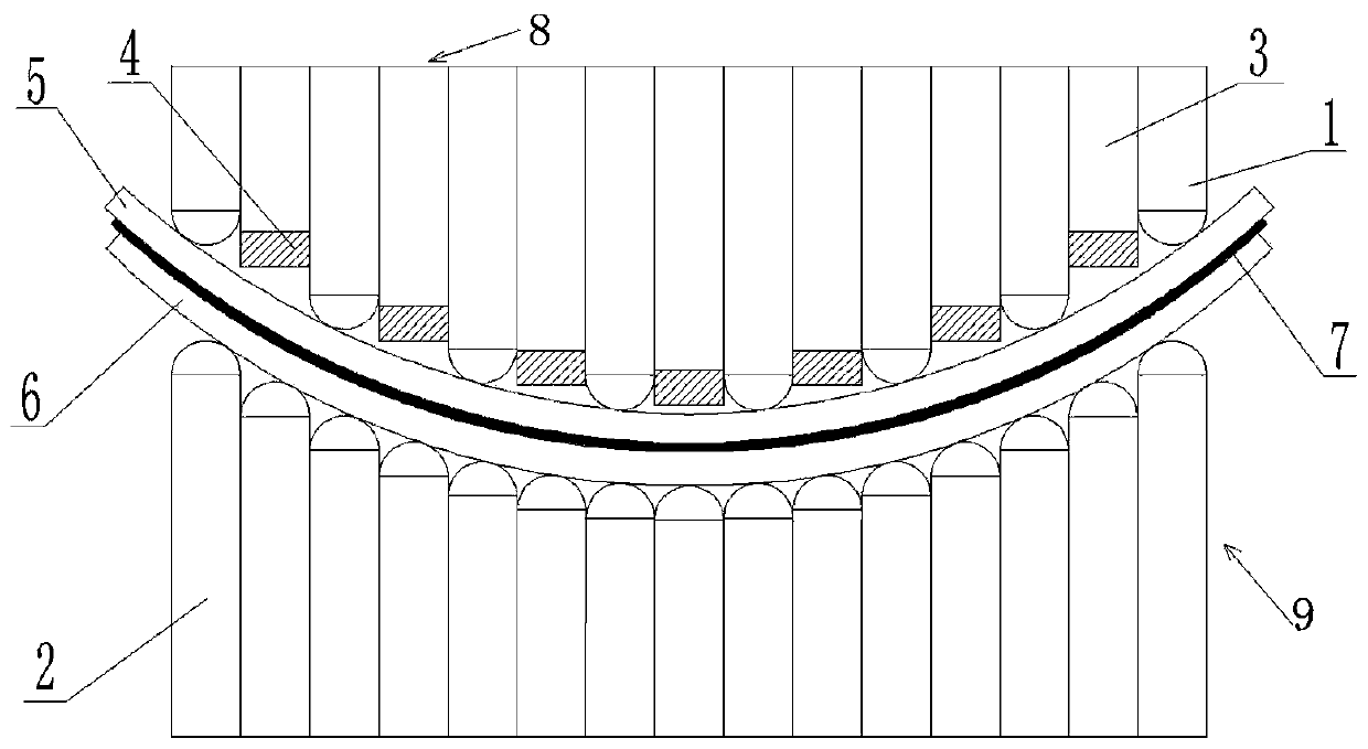
[0050] Such as Figure 1a-Figure 1d As shown, the embodiment of the present invention first discloses an electromagnetic-multipoint composite forming device for sheet metal, which includes an upper punch 1 and a lower punch 2. A plurality of upper punches 1 are arrayed to form a punch 8. An array of punches 2 forms a concave die 9, wherein the upper punch 1 and the lower punch 2 are driven up and down by a computer-controlled hydraulic cylinder. The punch 8 is provided with an upper coil support rod 3 that can move up and down. Similarly, the upper coil supports The rod 3 is also driven by a hydraulic cylinder to move up and down. The lower end of the upper coil support rod 3 is provided with an electromagnetic coil 4 that can shape the plate 7 so that the electromagnetic force of the electromagnetic coil 4 drives the plate to deform at a high rate. Specifically, in order to ensure uniform deformation of the sheet material 7, the upper coil support rod 3 and the upper punch 2 ar...
Embodiment 2
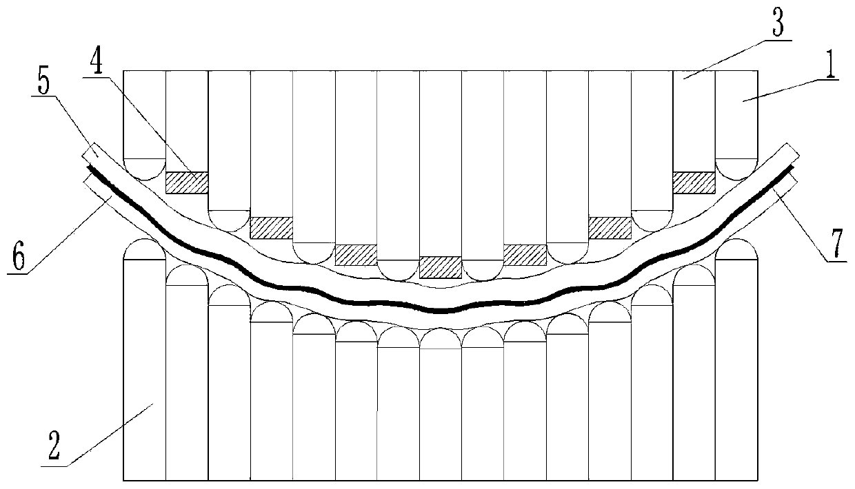
[0060] Such as Figure 2a-Figure 2f As shown, the structure of the male mold 8 in this embodiment is basically the same as that of the first embodiment, except that: in this embodiment, the female mold 9 is provided with a lower coil support rod 10 that can move up and down. The upper end of 10 is provided with an electromagnetic coil 4 that can be formed on the plate 7. When the plate 7 is punched, the electromagnetic coil 4 of the punch 8 and the die 9 is discharged twice, and the electromagnetic coil 4 is formed on the upper end of the lower punch 2. Down side. As a result, the electromagnetic coils on the male mold 8 and the female mold 9 complement each other for the sheet material 7 to further improve the forming efficiency and quality of the sheet material 7.
Embodiment 3
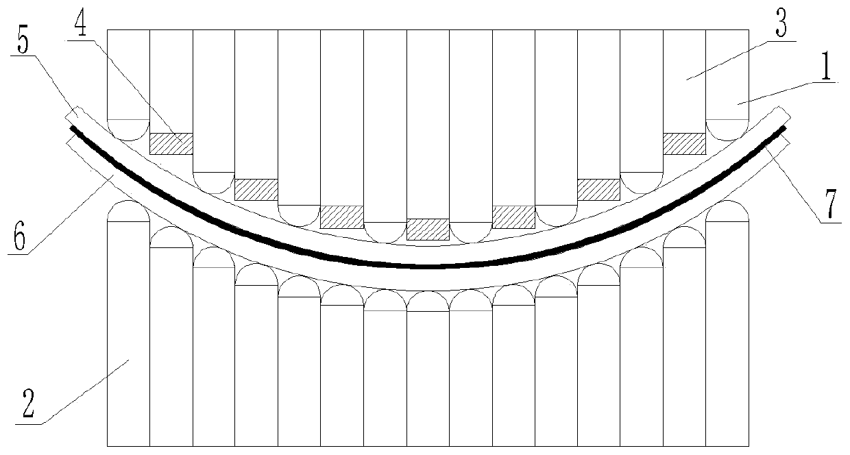
[0062] Such as Figure 3a As shown, the structure of the male mold 8 and the female mold 9 in this embodiment is basically the same as that of the second embodiment, the difference is: in this embodiment, the electromagnetic coil 4 on the male mold 8 and the electromagnetic coil on the female mold 9 4 are arranged alternately from the inside to the outside, so that the electromagnetic coil 4 can fully cover the forming surface of the plate 7 and further improve the forming efficiency and quality of the plate 7.
PUM
 Abstract
Description
Claims
Application Information