Magnetic pulse flanged hole method for shells

A technology of shell parts and magnetic pulses is applied in the field of plastic forming and manufacturing of metal sheets, which can solve the problems of complex process, long production cycle and low production efficiency, and achieve the effects of simplified process, short forming cycle and high yield.

Active Publication Date: 2017-01-04
HARBIN INST OF TECH +1
View PDF8 Cites 15 Cited by
  • Summary
  • Abstract
  • Description
  • Claims
  • Application Information

AI Technical Summary

Problems solved by technology

[0003] In order to solve the problems of complex process, low production efficiency and long production cycle in the process of making flanging holes by the existing steel mold turning method, the invention provides a magnetic pulse hole turning forming method for shell parts

Method used


Image

  • Magnetic pulse flanged hole method for shells
  • Magnetic pulse flanged hole method for shells
  • Magnetic pulse flanged hole method for shells

Examples


specific Embodiment approach 1

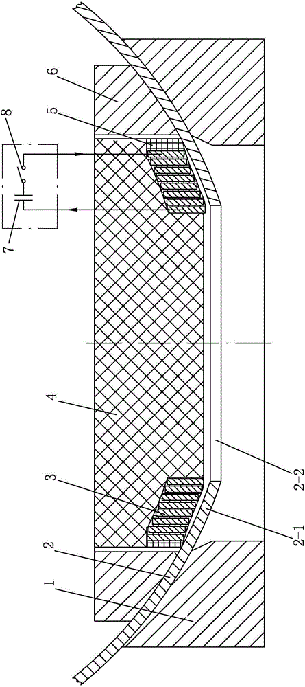
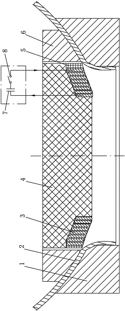
[0013] Specific implementation mode one: combine Figure 1-Figure 4 Explain, a kind of magnetic pulse hole turning forming method of shell parts, it comprises the following steps:

[0014] Step 1. Design the shape of the hole turning coil 3 according to the curved shell part 2 that has processed the prefabricated hole 2-2;

[0015] Step 2. Place the curved shell part 2 that has processed the prefabricated hole 2-2 on the hole forming die 1. The inner surface of the curved shell part 2 is provided with a blank holder 6 along the circumferential direction, and the hole forming die is 1 and the blank holder 6 clamp the curved shell part 2, and reserve the hole-turning deformation area 2-1. 2-1 Matching hole-turning coil 3, hole-turning coil 3 covers and sticks to the hole-turning deformation area 2-1, hole-turning coil 3 is coaxially arranged with prefabricated hole 2-2, and the hole-turning coil is made of rectangular cross-section copper turns Winding;

[0016] One end of th...

specific Embodiment approach 2

[0026] Embodiment 2: The difference between this embodiment and Embodiment 1 is that in step 2, the capacitor bank 7 is charged to 1kV-20kV. The induced current in the deformation zone will also generate an induced magnetic field. The coil current magnetic field and the induced current magnetic field are strengthened between the coil and the deformation area of ​​the curved surface part, and through the interaction with the induced current, a normal strong pulse magnetic field force acting on the deformation area of ​​the curved surface part is generated, which meets the design requirements and actual needs. Others are the same as in the first embodiment.

specific Embodiment approach 3

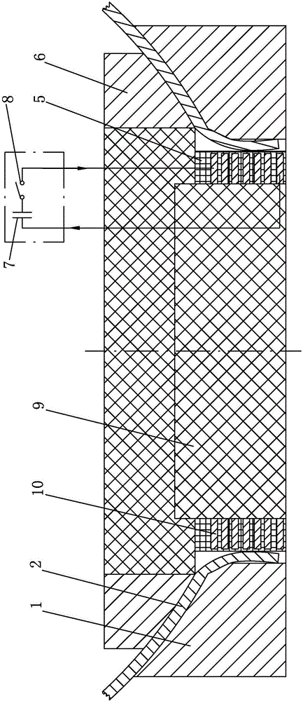
[0027] Embodiment 3: The difference between this embodiment and Embodiment 1 or 2 is that in Step 4, the capacitor bank 7 is charged to 1kV-20kV. Such setting is conducive to the generation of large pulse current and the radial pulse load acting on the straight wall of the flanged hole, causing it to produce high-speed radial deformation, thereby reducing the inclination angle and eliminating the bulge, so as to realize the molding. Meet the design requirements and actual needs. Others are the same as in the first or second embodiment.


PUM

PropertyMeasurementUnit
thicknessaaaaaaaaaa

Abstract

The invention relates to shell flanged hole part forming methods, in particular to a magnetic pulse flanged hole forming method for shells. The method aims at solving the problems that in the flanged hole manufacturing process of an existing steel die hole flanging method, the technology is complex, the production efficiency is low, and the production cycle is long. The method comprises the steps that firstly, the shape of a flanged hole coil bobbin is designed according to a curved surface shell with pre-manufactured holes; secondly, the curved surface shell with the pre-manufactured holes is arranged on a flanged hole forming female die, an edge pressing ring is arranged on the inner surface of the curved surface shell in the periphery direction, a hole flanging coil matched with the hole flanging deforming area is wound on the flanged hole coil bobbin, covers the hole flanging deforming area and is attached to the hole flanging deforming area, one end of a capacitor set is connected with one terminal of the hole flanging coil, the other end of the capacitor set is connected with one end of a gap switch, the other end of the gap switch is connected with the other terminal of the hole flanging coil, and the capacitor set is charged to reach the preset voltage value; thirdly, magnetic pulse flanged hole forming is carried out; fourthly, flanged holes are corrected. The method is used for forming flanged hole parts of shells.

Description

technical field [0001] The invention relates to a method for forming a hole-turning part of a shell, relates to a hole-turning forming process for various parts with high forming difficulty and high forming quality requirements, and belongs to the field of plastic forming and manufacturing of metal plates. Background technique [0002] In aerospace vehicles, there are generally holes formed on curved surfaces or planar shell parts. For example, in the bottom plate and side walls of fuel tanks of general liquid rocket engines, pipes and tanks need to be used Welding method connection, in order to create better conditions for welding, improve welding quality and strength, it is necessary to make a high-quality flanging hole on the box body. The conventional flanging method is to directly turn the hole with a steel mold. This method requires a set of large-scale forming tooling with convex and concave dies and a large table press, and the production cost is high and the cycle i...

Claims


Application Information

Patent Timeline
Patent Type & Authority Applications(China)
IPC IPC(8): B21D26/14
Inventor 于海平马继山王手龙郝晶董淑辉
Owner HARBIN INST OF TECH
Why Eureka
Try Eureka