Supercharge Your Innovation With Domain-Expert AI Agents!

Working method for building steel tube column welding auxiliary device

A technology for auxiliary devices and working methods, applied in the direction of auxiliary devices, welding/cutting auxiliary equipment, welding equipment, etc., can solve problems such as inability to clamp pipes, inability to weld electric and full welding, and inability to adjust welding angles, etc., to speed up clamping Efficiency, the effect of avoiding thermal deformation

Active Publication Date: 2020-05-19
FU JIAN ER JIAN JIAN SHE JI TUAN GONG SI
View PDF5 Cites 3 Cited by
  • Summary
  • Abstract
  • Description
  • Claims
  • Application Information

AI Technical Summary

Problems solved by technology

[0002] For example, Patent No. CN201712066540.5 is a kind of construction steel pipe column welding auxiliary device, which includes an upper steel pipe column, a locking device, a fixed block, a bolt 1, a fixing rod, a positioning base plate, a lower steel pipe column, a reinforcing rib plate 1, a spirit level, an arc plate and Reinforcing rib plate II, the locking device adopts two pieces, which are respectively installed on the outer sides of the steel pipe column of the upper section and the steel pipe column of the lower section, and are connected to the locking device through a fixing rod; the fixing block is installed on the outer side of the locking device, and Evenly arranged around the circumference, the center of the fixed block is processed with a round hole, and the side wall is processed with a wire hole connected with the round hole; the utility model locking device, the setting of the fixing rod, this device is conducive to ensuring the steel pipe column pairing Concentricity, prevent welding deformation of steel pipe columns, ensure installation accuracy and engineering quality; the disadvantage of this utility model is that it cannot clamp pipes with different diameters, nor can it adjust the welding angle, and it cannot perform electric welding and full welding according to the needs of use.

Method used


Image

  • Working method for building steel tube column welding auxiliary device
  • Working method for building steel tube column welding auxiliary device
  • Working method for building steel tube column welding auxiliary device

Examples


specific Embodiment approach 1

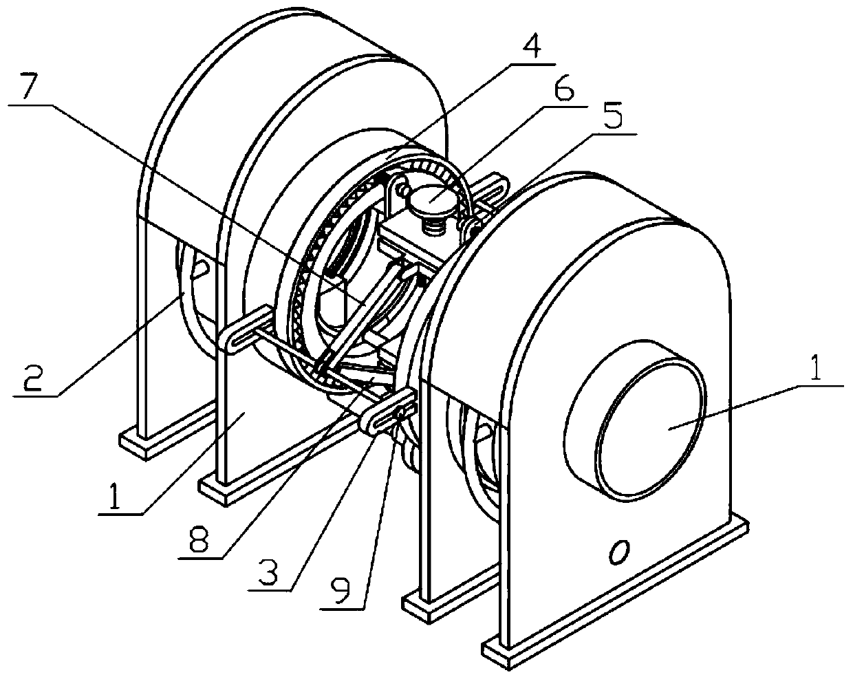
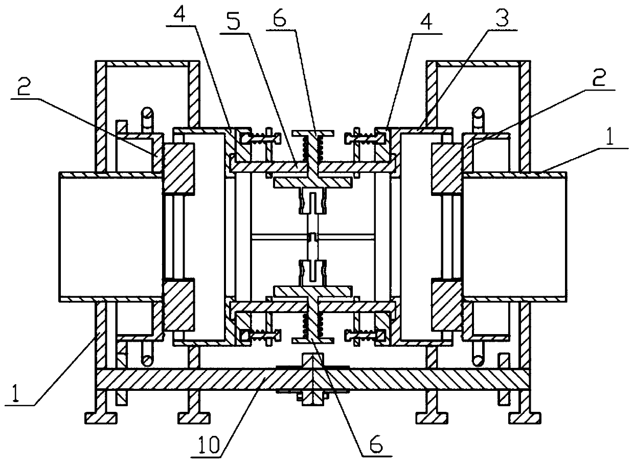
[0033] Combine below Figure 1-12 Describe this embodiment, an auxiliary device for welding steel pipe columns in construction, including a side bracket 1, a rotating mechanism 2, a clamping mechanism 3, an angle plate 4, a welding bracket 5, a pushing mechanism 6, a connecting rod I7, a connecting rod II8, and a hinged column 9 and the power connection mechanism 10, the side bracket 1, the rotating mechanism 2, the clamping mechanism 3 and the angle plate 4 are all symmetrically provided with two left and right, and the two rotating mechanisms 2 are respectively rotated and connected in the two side brackets 1, and the two Two clamping mechanisms 3 are respectively fixedly connected to the inner sides of the two side brackets 1, two angle plates 4 are respectively fixedly connected to the two clamping mechanisms 3, and the welding bracket 5 and the pushing mechanism 6 are arranged symmetrically up and down. The left and right ends of each welding bracket 5 are slidably connec...

specific Embodiment approach 2

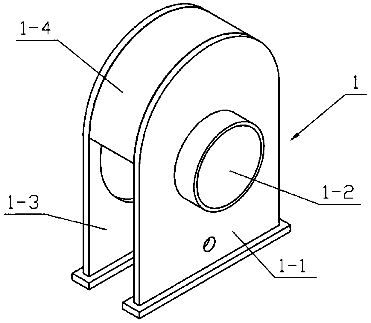
[0035] Combine below Figure 1-12 This embodiment will be described. This embodiment will further describe Embodiment 1. The side bracket 1 includes an outer plate 1-1, a support cylinder 1-2, an inner plate 1-3, and a connecting plate 1-4. The connecting plate 1-4 The two ends of the inner plate 1-3 and the upper end of the outer plate 1-1 are respectively fixedly connected, and the support cylinder 1-2 is fixedly connected to the middle end of the outer plate 1-1; when in use, the two pipes to be welded are respectively placed on the two Inside a support tube 1-2.

specific Embodiment approach 3

[0037] Combine below Figure 1-12 Describe this embodiment, this embodiment will further explain the second embodiment, the rotating mechanism 2 includes a rotating support plate 2-1, a rotating cylinder 2-2, a rotating column 2-3, a rotating handle 2-4 and a ring gear 2 -5, the rotating support plate 2-1 is provided with a spiral thread, one end of the rotating cylinder 2-2 is fixedly connected to the outer side of the rotating supporting plate 2-1, and the ring gear 2-5 is fixedly connected to the other end of the rotating cylinder 2-2 The outer side of the rotating column 2-3 is evenly arranged in a plurality of circumferential directions, the inner sides of the plurality of rotating columns 2-3 are fixedly connected to the outer side of the rotating cylinder 2-2, and the rotating handle 2-4 is fixedly connected to the plurality of rotating columns 2 -3 on the outside, the two rotating support plates 2-1 are respectively rotatably connected to the inner sides of the two sup...


PUM


Abstract

The invention relates to an auxiliary device, in particular to a working method for a building steel tube column welding auxiliary device. The building steel tube column welding auxiliary device comprises side brackets, rotary mechanisms, clamping mechanisms, angle plates, a welding bracket, a pushing mechanism, a connecting rod I, a connecting rod II, a hinged column and a power connecting mechanism, wherein the two side brackets, the two rotary mechanisms, the two clamping mechanisms and the two angle plates are symmetrically arranged left and right; the two rotary mechanisms are separatelyconnected in the two side brackets rotatably; the two clamping mechanisms are fixedly connected to the inner sides of the two side brackets separately; and tubes of different diameters can be clampedthrough the clamping mechanisms at the two sides; and the clamping mechanisms at the two sides can be linked through the power connecting mechanism to quicken clamping efficiency; and two welding arc-shaped plates at the two sides separately slide in the two mounting slots to realize regulating a welding angle according to use needs; and through the connecting rod I, the connecting rod II and thehinged column, welding can be performed simultaneously at the two sides to avoid thermal deformation, so that spot welding and full welding can be performed according to the use needs.

Description

technical field [0001] The invention relates to an auxiliary device, in particular to a working method of a construction steel pipe column welding auxiliary device. Background technique [0002] For example, Patent No. CN201712066540.5 is a kind of construction steel pipe column welding auxiliary device, which includes an upper steel pipe column, a locking device, a fixed block, a bolt 1, a fixing rod, a positioning base plate, a lower steel pipe column, a reinforcing rib plate 1, a spirit level, an arc plate and Reinforcing rib plate II, the locking device adopts two pieces, which are respectively installed on the outer sides of the steel pipe column of the upper section and the steel pipe column of the lower section, and are connected to the locking device through a fixing rod; the fixing block is installed on the outer side of the locking device, and Evenly arranged around the circumference, the center of the fixed block is processed with a round hole, and the side wall i...

Claims


Application Information

Patent Timeline
Patent Type & Authority Applications(China)
IPC IPC(8): B23K37/053
CPCB23K37/0533
Inventor 不公告发明人
Owner FU JIAN ER JIAN JIAN SHE JI TUAN GONG SI
Features
  • R&D
  • Intellectual Property
  • Life Sciences
  • Materials
  • Tech Scout
  • Unparalleled Data Quality
  • Higher Quality Content
  • 60% Fewer Hallucinations
Learn More