
Positioning jig

A technology of positioning jig and pressing claw, which is used in positioning devices, manufacturing tools, metal processing machinery parts, etc., can solve problems such as poor surface finish of finished products, reducing the yield of workpieces to be processed, and affecting the installation process.

Inactive Publication Date: 2020-05-19
BEIJING XIAOMI MOBILE SOFTWARE CO LTD
View PDF6 Cites 2 Cited by
  • Summary
  • Abstract
  • Description
  • Claims
  • Application Information

AI Technical Summary

Problems solved by technology

[0006] Deformation often occurs during the process of positioning the workpiece to be processed along the Z-axis direction, and the surface of the finished product after blanking is poor, which reduces the yield of the workpiece to be processed and affects the subsequent installation process

Method used


Image

  • Positioning jig
  • Positioning jig
  • Positioning jig

Examples


Embodiment Construction

[0040] Reference will now be made in detail to the exemplary embodiments, examples of which are illustrated in the accompanying drawings. When the following description refers to the accompanying drawings, the same numerals in different drawings refer to the same or similar elements unless otherwise indicated. The implementations described in the following exemplary examples do not represent all implementations consistent with the present disclosure. Rather, they are merely examples of apparatuses and methods consistent with aspects of the present disclosure as recited in the appended claims.

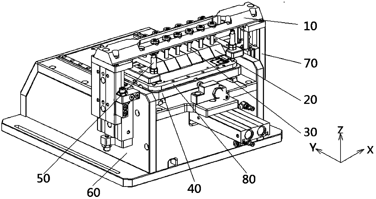
[0041] The disclosure provides a positioning jig, which can be used to position the host of electronic devices such as mobile phones and tablets during processing. The X-axis of the positioning jig" and the "Y-axis of the positioning jig" are perpendicular to each other and form a plane perpendicular to the Z-axis. The left and right directions are taken as an example for description....


PUM


Abstract

The invention relates to a positioning jig. The positioning jig comprises a pressing assembly, wherein the pressing assembly is used for pressing a workpiece to be processed in the Z-axis direction ofthe positioning jig, the pressing assembly comprises a plurality of pressing claws and a plurality of elastic parts, the plurality of elastic parts are arranged corresponding to the plurality of pressing claws and apply elastic force in the Z-axis direction to the plurality of pressing claws, and the plurality of pressing claws are used for elastically pressing the workpiece to be processed. Wheneach pressing claw is in press fit with the corresponding part of the workpiece to be processed, the elastic parts have the elastic force and displacement in the Z-axis direction, the pressing clawscorresponding to the elastic parts have different displacement relative to a cross beam, the pressing claws make contact with the parts of the workpiece to be processed, and it is guaranteed that allthe parts of the workpiece to be processed are pressed in place, so that deformation caused by large press fit state difference among the different parts of the workpiece to be processed is avoided.

Description

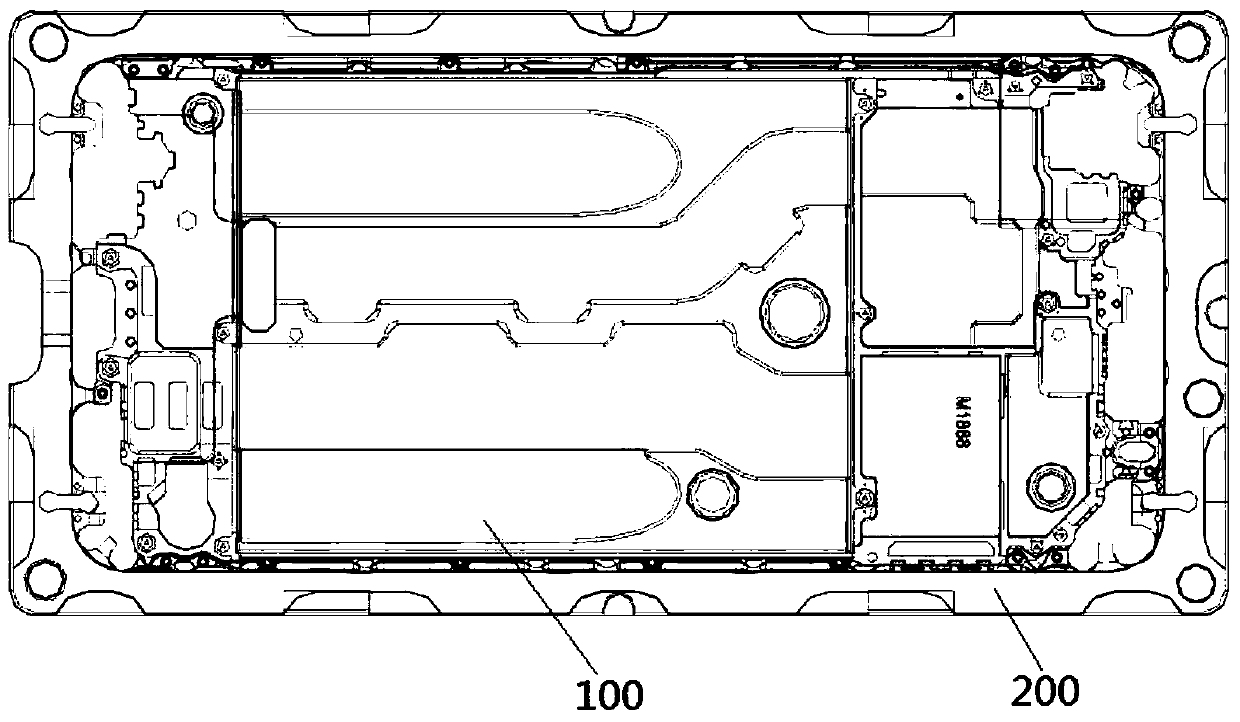
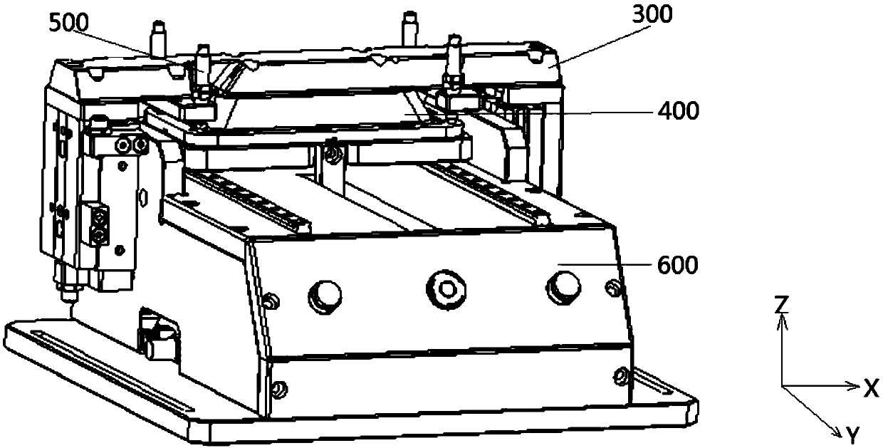
technical field [0001] The present disclosure relates to the technical field of mechanical processing, in particular to a positioning jig. Background technique [0002] Such as figure 1 As shown, in the process of processing the mainframe of electronic equipment such as mobile phones and tablets, the middle plate structure 100 is first formed through the die-casting process, and then the middle plate structure 100 is welded to the frame 200, and then the positioning jig of the processing machine tool is used to form the middle plate structure. The integral part formed by 100 and frame 200 is positioned along the Z-axis direction of the machine tool. [0003] Such as figure 2 As shown, the existing positioning jig has a jig body 600 , a moving beam 300 , pressing jaws 400 and supporting columns 500 , wherein there is one pressing jaw 400 and four supporting columns 500 . The beam 300 is installed on the jig body 600 and can move along the Z-axis direction. The support co...

Claims


Application Information

Patent Timeline
IPC IPC(8): B23Q3/06
CPCB23Q3/06
Inventor 薛朝坡左永强王东亮
Owner BEIJING XIAOMI MOBILE SOFTWARE CO LTD
Learn More