
Efficient dicing machine

A dicing machine, high-efficiency technology, applied in metal processing and other directions, can solve the problems of adjusting the overall thickness of the material, low practicability, and difficulty in adjusting the cutting thickness of the cutting edge slicing knife, etc., to achieve the effect of improving practicability

Pending Publication Date: 2020-05-19
广东志伟妙卓智能机械制造有限公司
View PDF0 Cites 0 Cited by
  • Summary
  • Abstract
  • Description
  • Claims
  • Application Information

AI Technical Summary

Problems solved by technology

[0003] Due to the fixed size of the cutting opening in the existing dicing machine, it is difficult to adjust the size of the cutting opening to change the cutting thickness of the material by the slicing knife, so it is difficult to adjust the overall thickness of the material according to actual needs, and the practicability is not high

Method used


Image

  • Efficient dicing machine
  • Efficient dicing machine
  • Efficient dicing machine

Examples


Embodiment 1

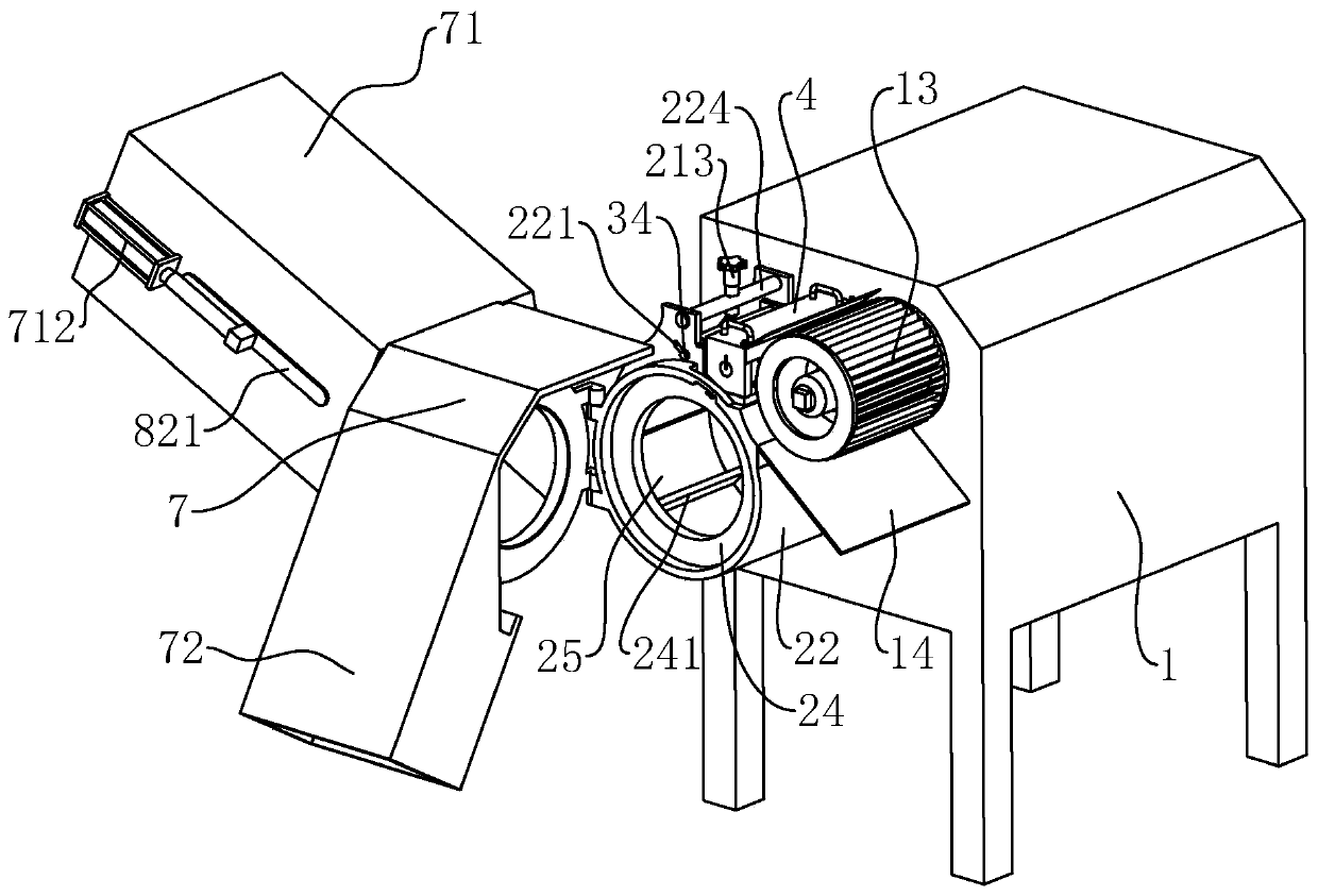
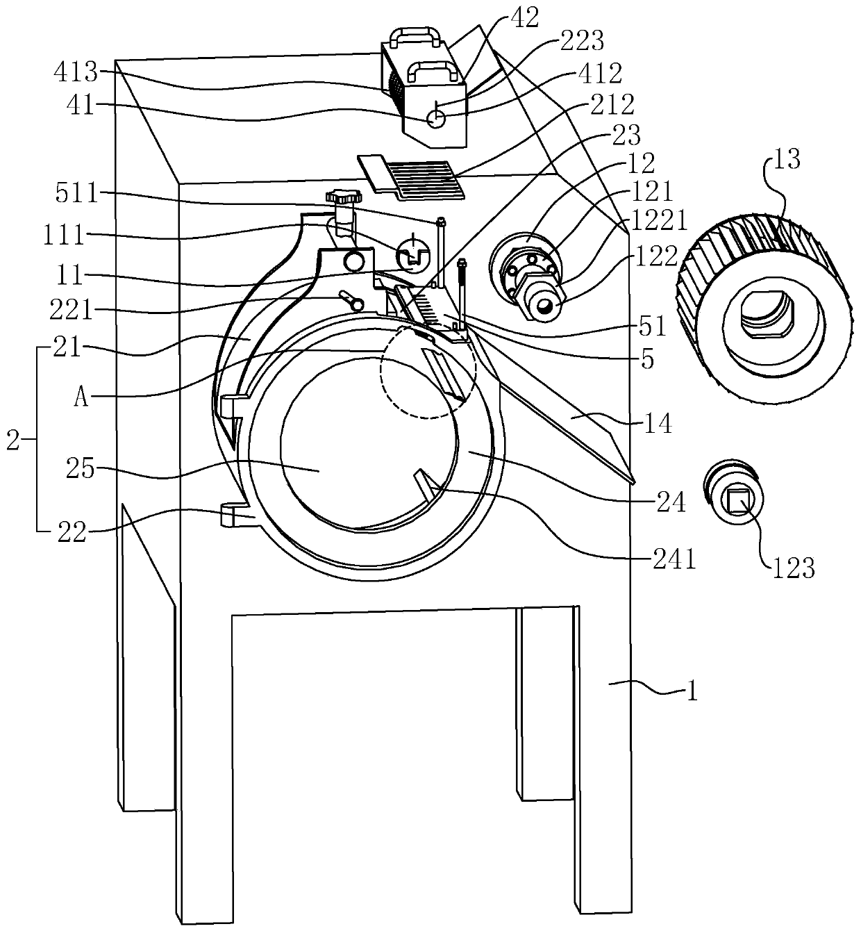
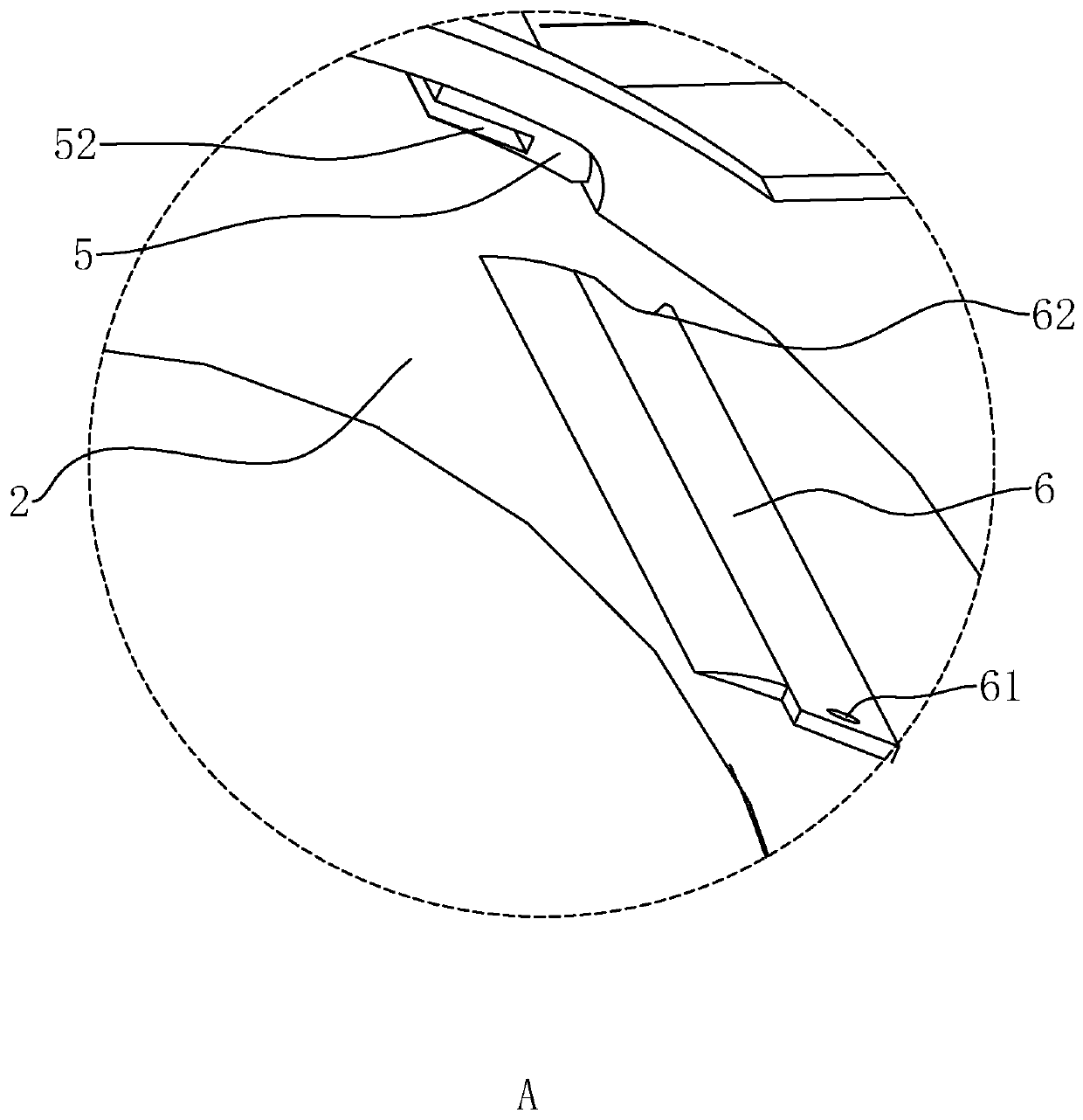
[0040] refer to figure 1 , figure 2 and image 3 , a high-efficiency dicing machine disclosed by the present invention, comprising a body 1, a feeding part, a cutting part and a discharging part are installed on one side of the body 1, and the feeding part includes a cylindrical material guide cylinder 2 and a propeller 24. The material guide cylinder 2 is fixed on the side wall of the machine body 1, and the side of the material guide cylinder 2 facing away from the machine body 1 is provided with a feed port 25, and the propeller 24 is rotatably installed inside the material guide cylinder 2. The side wall of material guide cylinder 2 is provided with strip-shaped cutout 23, and cutting portion comprises the slicer knife 6 that is installed on one side of cutout 23 and circle cutter holder 4 successively, and circle cutter holder 4 is installed by rotating shaft 41 with multiple A circle cutter 413. The discharge part includes a chopping knife cylinder 13 and a blanking ...

Embodiment 2

[0055] refer to Figure 7, the adjustment mechanism includes a worm wheel 32, a worm screw 211, two gears 33 and two arc racks 222, and the two arc racks 222 are respectively fixed on both sides of the top of the cylinder seat 22, and the center position of the arc rack 222 is the same as The hinge points of the barrel seat 22 and the upper cover 21 coincide with each other. The two gears 33 are respectively fixed on the two ends of the elevating rod 3 , and the gears 33 on the same side mesh with the arc-shaped rack 222 . The worm wheel 32 is fixed on the middle part of the lifting rod 3 , the worm screw 211 is rotatably mounted on the top of the upper cover 21 , and the worm screw 211 and the worm wheel 32 mesh with each other. Turning the worm 211 can drive the worm wheel 32 to rotate, and the worm wheel 32 can drive the lifting rod 3 and the gear 33 to rotate, and the gear 33 can rotate and move on the arc-shaped rack 222, which can drive the upper cover 21 to turn around...


PUM


Abstract

The invention relates to an efficient dicing machine which comprises a machine body, wherein the machine body is provided with a feeding part, a cutting part and a discharging part; the feeding part comprises a guiding cylinder and a propeller rotatably arranged in the guiding cylinder; the propeller is provided with a plurality of guiding plates; a cutting opening is formed in the side wall of the guiding cylinder; the guiding cylinder comprises a cylinder seat and an upper cover; the cylinder seat is rotatably connected with one side of the upper cover; the cylinder seat and the other side of the upper cover are positioned on the two sides of the cutting opening separately; a cutting part is positioned on one side of the cutting opening; the upper cover is rotatably provided with a lifting rod; the lifting rod is provided with an adjusting mechanism for adjusting the size of the cutting opening; and the lifting rod and the cylinder seat are mutually fixed through a fixing mechanism.The adjusting mechanism drives the upper cover to overturn around a rotary connecting point of the upper cover and the cylinder seat to adjust the space between the upper cover and the cutting part, so that the size of the cutting opening is changed, and the material cutting thickness can be adjusted as needed.

Description

technical field [0001] The invention relates to the technical field of food processing machinery, in particular to a high-efficiency dicing machine. Background technique [0002] The dicing machine is often used to cut edible crops such as fruits and vegetables into dices during deep processing. It is widely used in dehydrated vegetables, quick-frozen vegetable processing plants, soft food materials such as jelly jelly and honey, and food pickles. At present, the drum cutting method is generally used for dicing fruits and vegetables. The dicing part is composed of a slicing knife and a circular cutter. When working, the material is centrifugally moved through the high-speed rotating material guide plate, and the centrifugal force makes the material rotate close to the side wall of the material guide cylinder. , There is a strip-shaped cutting opening on the side wall of the material guide cylinder, and the part of the material protruding from the cutting opening is cut by a ...

Claims


Application Information

Patent Timeline
IPC IPC(8): B26D3/18B26D7/06B26D7/26
CPCB26D3/18B26D7/0641B26D7/0691B26D7/2614B26D7/2621B26D2210/02
Inventor 肖林华肖能武练文燕
Owner 广东志伟妙卓智能机械制造有限公司
Learn More