

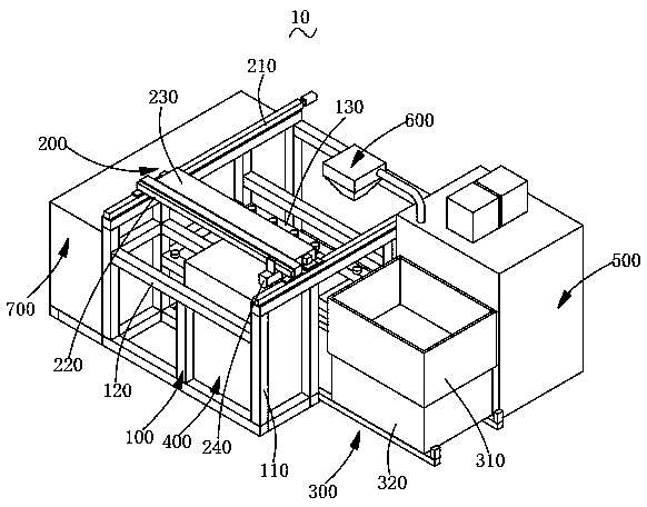
3D printing equipment
A 3D printing and equipment technology, applied in the field of additive manufacturing, can solve the problems of low printing efficiency and low product precision, and achieve the effect of improving printing efficiency, high printing accuracy and reducing positioning requirements
- Summary
- Abstract
- Description
- Claims
- Application Information
AI Technical Summary
Problems solved by technology
Method used
Image

Examples
Embodiment 1
[0034] At least one beam is arranged between the two blanking guide rails, and each beam is correspondingly installed with one printing guide rail. That is, the beam is a structure supporting and setting the printing guide rail. In this way, the installation of the printing guide rail can be facilitated more stably by arranging the beam, and it can effectively avoid being affected when the printing guide rail and the blanking guide rail move mutually. It should be noted that the printing guide rail can be directly set between the two blanking guide rails, that is, there is no need to set a beam support, but setting the beam can better ensure that the printing guide rail and the blanking guide rail are affected by each other during movement.
Embodiment 2
[0036] A beam is slidably disposed between the two blanking guide rails, and a blanking mechanism is provided on a side of the beam away from the printing guide rail. In this embodiment, the printing mechanism is integrated with the blanking mechanism through the beam, and the printing mechanism moves back and forth along the blanking guide rail together with the blanking mechanism. That is, during normal operation, the blanking mechanism moves along the AB direction for blanking. During this process, the printing mechanism moves along with the blanking mechanism, but the printing mechanism does not print, and the printing mechanism returns along the CD direction with the blanking mechanism. Print while moving. That is, the blanking operation is performed during the process of the blanking mechanism, and then the printing operation is performed during the return trip.
Embodiment 3
[0038] Two beams are slidably arranged between the two blanking guide rails, the blanking mechanism is arranged between the two beams, and each beam is installed on a side away from the blanking mechanism. the printing mechanism. In this embodiment, printing mechanisms are provided on both sides of the blanking mechanism respectively, and are integrated on the same blanking guide rail, and the two printing mechanisms move back and forth along the blanking guide rail together with the blanking mechanism. That is, in normal operation, when the blanking mechanism moves along the EF direction for blanking, the left printing mechanism moves with the blanking mechanism and prints; when the blanking mechanism returns to blanking along the GH direction, the right printing mechanism follows The blanking mechanism moves together and prints. That is, printing is performed while the blanking operation is being performed during the process of the blanking mechanism, and then the printing ...
PUM
 Abstract
Description
Claims
Application Information