Hydraulic power system for variable counterweight and lifting system with same
A technology of hydraulic power system and lifting system, applied in the field of lifting system, can solve problems such as loss, achieve the effect of reducing power and electric energy demand, balancing gravity imbalance, and convenient application
- Summary
- Abstract
- Description
- Claims
- Application Information
AI Technical Summary
Problems solved by technology
Method used
Image

Examples
Embodiment Construction
[0034] The core of the present invention is to provide a hydraulic power system for variable counterweight and a lifting system with the hydraulic power system. The power and electric energy requirements of the power source can ensure the stable operation of the lifting system.
[0035] In order to enable those skilled in the art to better understand the solution of the present invention, the present invention will be further described in detail below in conjunction with the accompanying drawings and specific embodiments.
[0036] For ease of understanding and brevity of description, the following description will be combined with the hydraulic power system and its lifting system, and the beneficial effects will not be discussed again.
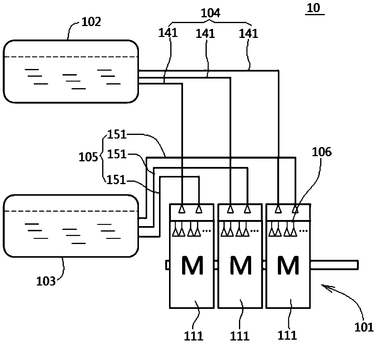
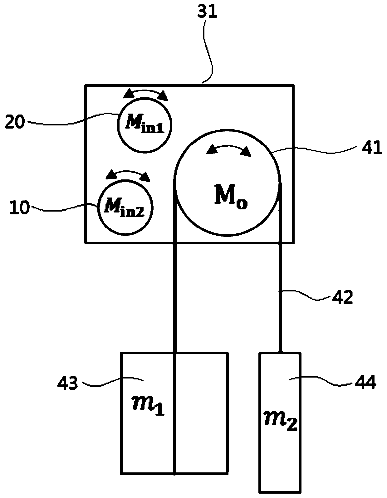
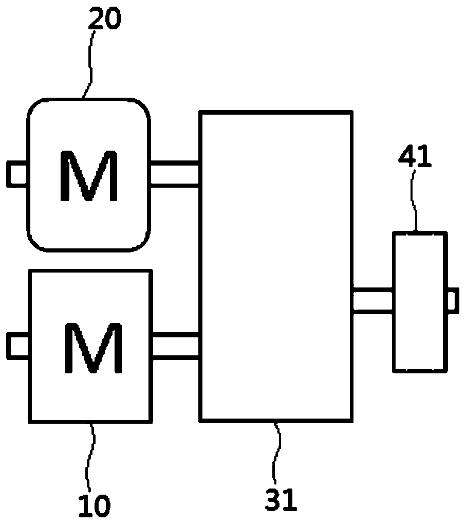
[0037] Please refer to figure 1 and figure 2 , figure 1 It is a structural schematic diagram of a specific embodiment of a hydraulic power system for variable counterweight of the lifting system provided by the present invention; figure ...
PUM
 Abstract
Description
Claims
Application Information
PatSnap Eureka turns technology decisions into work you can execute. Powered by our Innovation Knowledge Graph, it runs expert workflows across engineering, life sciences, materials and intellectual property. Get your review-ready output in minutes.


