Methods of handling wind turbine blades and mounting said blades on a wind turbine, system and gripping unit for handling a wind turbine blade

a technology of wind turbine blades and wind turbines, which is applied in the direction of propellers, propulsive elements, water-acting propulsive elements, etc., can solve the problems of complex lifting of the rotor to the nacelle, the difficulty of mounting the blade, so as to enhance the control of the movement and reduce the risk of blade damage, the effect of functional lifting

Inactive Publication Date: 2007-11-22
VESTAS WIND SYST AS
View PDF2 Cites 67 Cited by
  • Summary
  • Abstract
  • Description
  • Claims
  • Application Information

AI Technical Summary

Benefits of technology

[0059] In a fourteenth embodiment of the invention, said unit comprises two sets of clamping jaws. By using two sets of clamping jaws, a preferred relation between cost, functionality and safety of lifting is achieved.
[0060] In a fifteenth embodiment of the invention, said unit comprises a lever system comprising a lever arm and at least one weight. By using a lever system, it is possible to move the mass center of the wind turbine blade and gripping unit as one closer to the lifting positions and thus enhance control of the movement as well as make it easier on the lever system due to the force of gravity.
[0061] In a sixteenth embodiment of the invention, said lever system further c

Problems solved by technology

The usual way comprises a number of disadvantages which have become more and more problematic with the increasing size and weight of the wind turbine rotor.
Especially assembly of the wind turbine rotor on the ground is problematic as it requires a large area free of obstacles, which is planar and stable in order to

Method used


Image

  • Methods of handling wind turbine blades and mounting said blades on a wind turbine, system and gripping unit for handling a wind turbine blade
  • Methods of handling wind turbine blades and mounting said blades on a wind turbine, system and gripping unit for handling a wind turbine blade
  • Methods of handling wind turbine blades and mounting said blades on a wind turbine, system and gripping unit for handling a wind turbine blade

Examples


Embodiment Construction

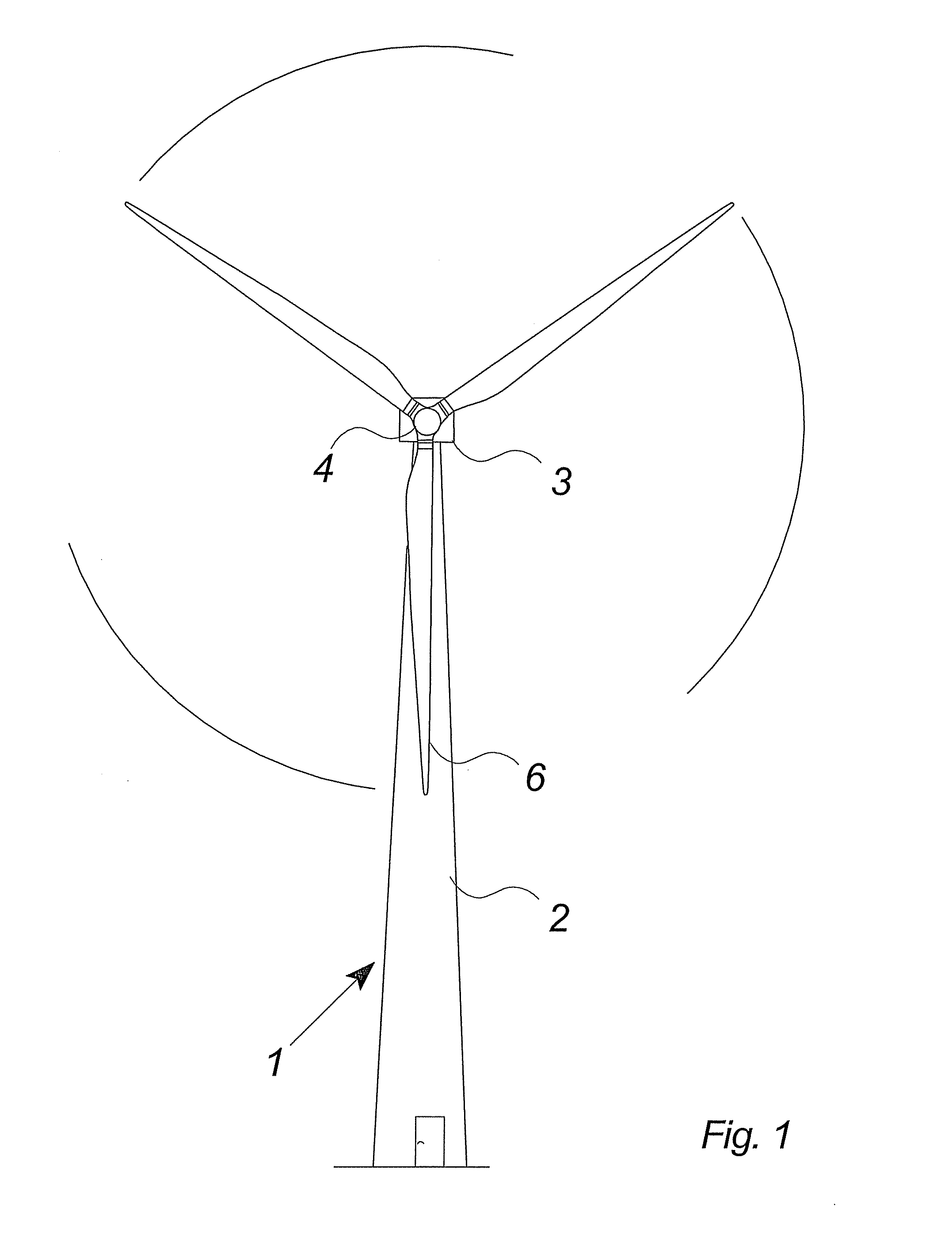
[0075]FIG. 1 shows a modern wind turbine 1 with a tower 2 and a wind turbine nacelle 3 positioned on top of the tower. The wind turbine rotor 5 is connected to the nacelle through the low speed shaft 6 extending from the nacelle front (shown in FIG. 2a).

[0076] As illustrated in the figure, winds over a certain level will activate the rotor and allow it to rotate perpendicularly to the wind. The rotation movement is converted into electric power which is usually supplied to the transmission grid as will be known by persons skilled within the area.

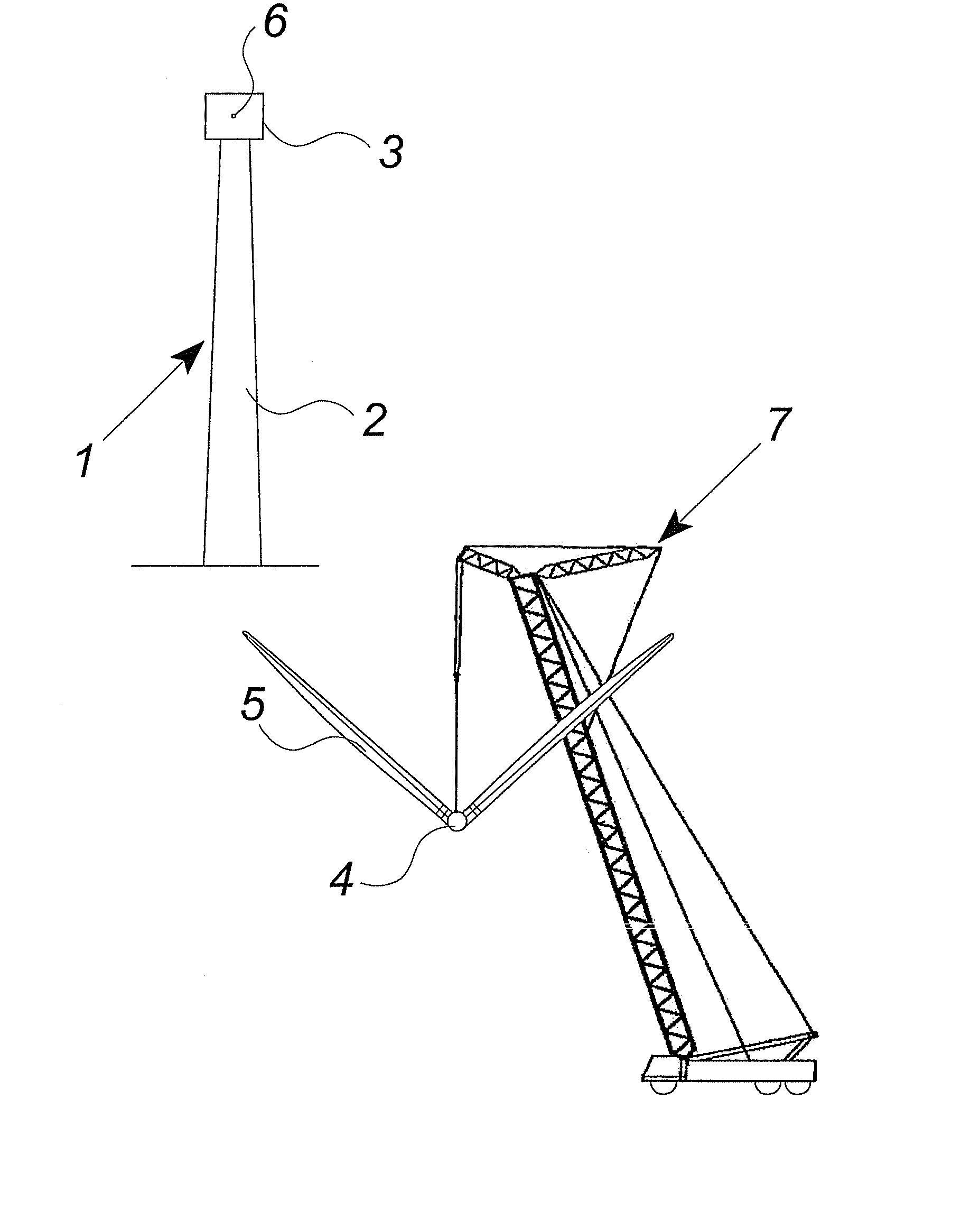
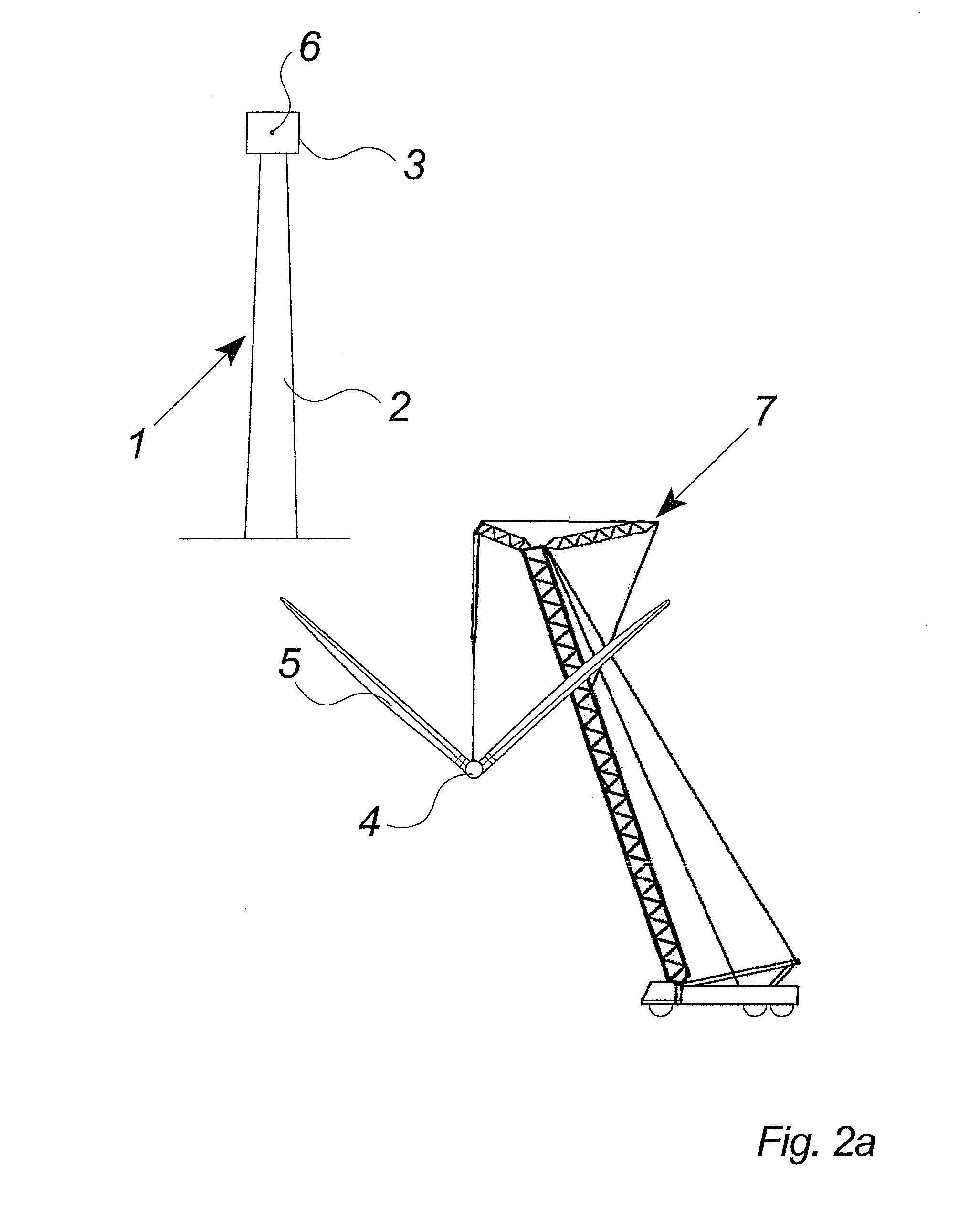
[0077] The FIGS. 2a to 2c show the different steps of lifting and mounting a wind turbine hub and three wind turbine blades according to a preferred embodiment of the invention. The wind turbine may be an on-shore or an off-shore wind turbine in which the different positions cause different problems such as the ground space within which the mounting of the rotor can be performed.

[0078]FIG. 2a shows a crane 7 lifting the rotor 5, said roto...


PUM

PropertyMeasurementUnit
Weightaaaaaaaaaa
Sizeaaaaaaaaaa
Flexibilityaaaaaaaaaa

Abstract

The invention relates to methods of handling wind turbine blades and mounting said blades on a wind turbine, said method comprising the steps of lifting a wind turbine hub to the nacelle of wind turbine with a lifting system and mounting the hub on the nacelle. Further, the method comprises the steps of gripping at least one wind turbine blade with a lifting system including at least one gripping unit for handling wind turbine blades, lifting said at least one wind turbine blade into close proximity to said hub, and mounting said at least one wind turbine blade on said hub. The invention also relates to a gripping unit for handling a wind turbine blade during transport.

Description

CROSS REFERENCE TO RELATED APPLICATION [0001] This application is a continuation of, and claims the benefit of, U.S. application Ser. No. 10 / 503,192 filed on 30 Jun. 2004, the entire contents of which are herein incorporated by reference.BACKGROUND OF THE INVENTION [0002] The invention relates to methods of handling wind turbine blades and mounting said blades on a wind turbine, and a system and gripping unit for handling a wind turbine blade. [0003] Modern wind turbines usually comprise a rotor with a considerable diameter and weight, as illustrated in FIG. 1. The diameter of modern rotors is approaching 100 to 150 meters and the rotor including the wind turbine hub and e.g. three wind turbine blades may add up to around 40 to 50 tons. [0004] The usual way of mounting a wind turbine includes the steps of transporting the different elements to the site of the wind turbine, assembling the tower sections and the tower, lifting the wind turbine nacelle with a crane and mounting the nac...

Claims


Application Information

Patent Timeline
IPC IPC(8): B23P21/00
CPCF03D1/0658Y02E10/721Y10S416/05Y10T29/49826Y10T29/53Y02E10/72
Inventor BERVANG, ANDERS GREVE
Owner VESTAS WIND SYST AS
Why Eureka
Try Eureka