Gas-pressurized lubricator

Inactive Publication Date: 2006-05-25
WEATHERFORD TECH HLDG LLC
View PDF4 Cites 64 Cited by
  • Summary
  • Abstract
  • Description
  • Claims
  • Application Information

AI Technical Summary

Benefits of technology

[0020] In one aspect, embodiments of the present invention generally provide a lubricator for reducing a kinetic energy of a plunger at a surface of a wellbore in a plunger lift system, comprising a generally tubular body having a bore therethrough, the bore closed at an end portion thereof; a striker assembly within the bore having a sealed relationship with the tubular body and movable with respect to the tubular body; and a pressurized, sealed chamber formed within the bore between the closed portion and the striker assembly to reduce the kinetic energy of the plunger at the surface. In another aspect, embodiments of the present invention provide a lubricator for reducing shock of a plunger within a plunger lift system upon impact with a kinetic energy-decreasing surface within t

Problems solved by technology

Often, pressure within the wellbore is insufficient to cause the production fluid to naturally rise through the production tubing to the surface of the wellbore.
Using the bumper spring within the lubricator to absorb the shock of the plunger on its up-stroke is problematic because of additional safety hazards which occur with use of the lubricator as well as because of decreased profitability of the well with use of the lubricator.
The force of impact of the plunger against the spring often causes the bumper spring to fail, break, or become otherwise damaged.
Damage to the spring may require replacement of the spring, decreasing the profits of the well because of down-time during spring replacement.
Additionally, damage to the spring may decrease the shock absorption ability of the spring, eventually causing the plunger to blow out the cap and exit the lubricator into the atmosphere.
Blowing off the cap from the lubricator creates a safety hazard and usually causes damage to the lubricator, also decreasing the profitability of the well due to down-time to replace or repair the lub

Method used


Image

  • Gas-pressurized lubricator
  • Gas-pressurized lubricator
  • Gas-pressurized lubricator

Examples


Embodiment Construction

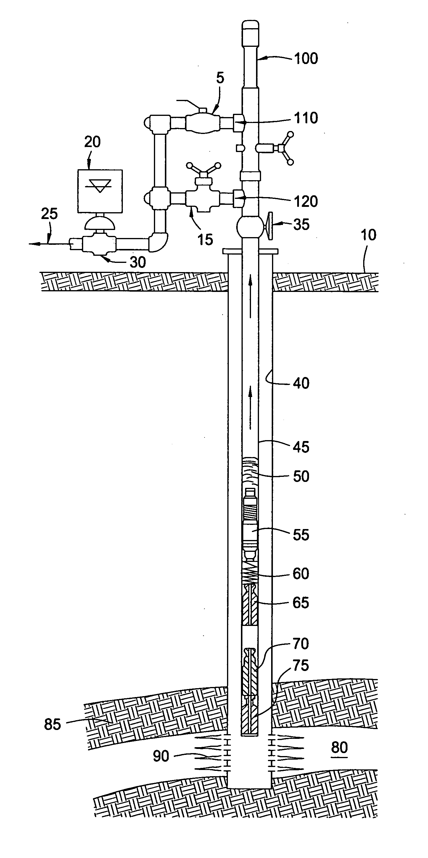
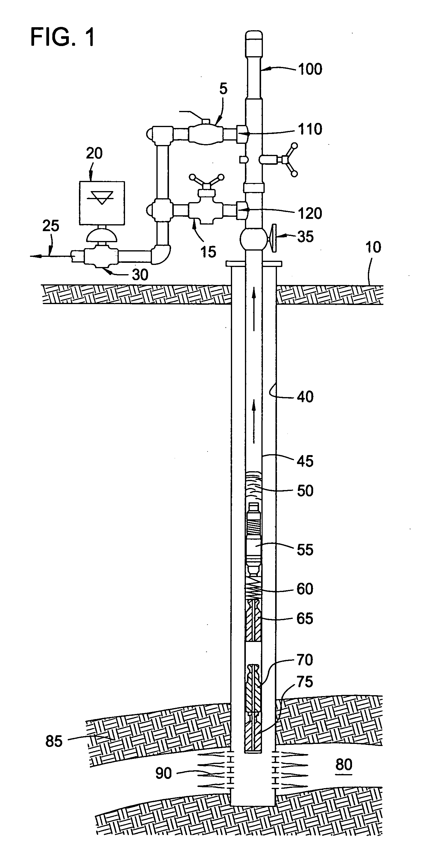
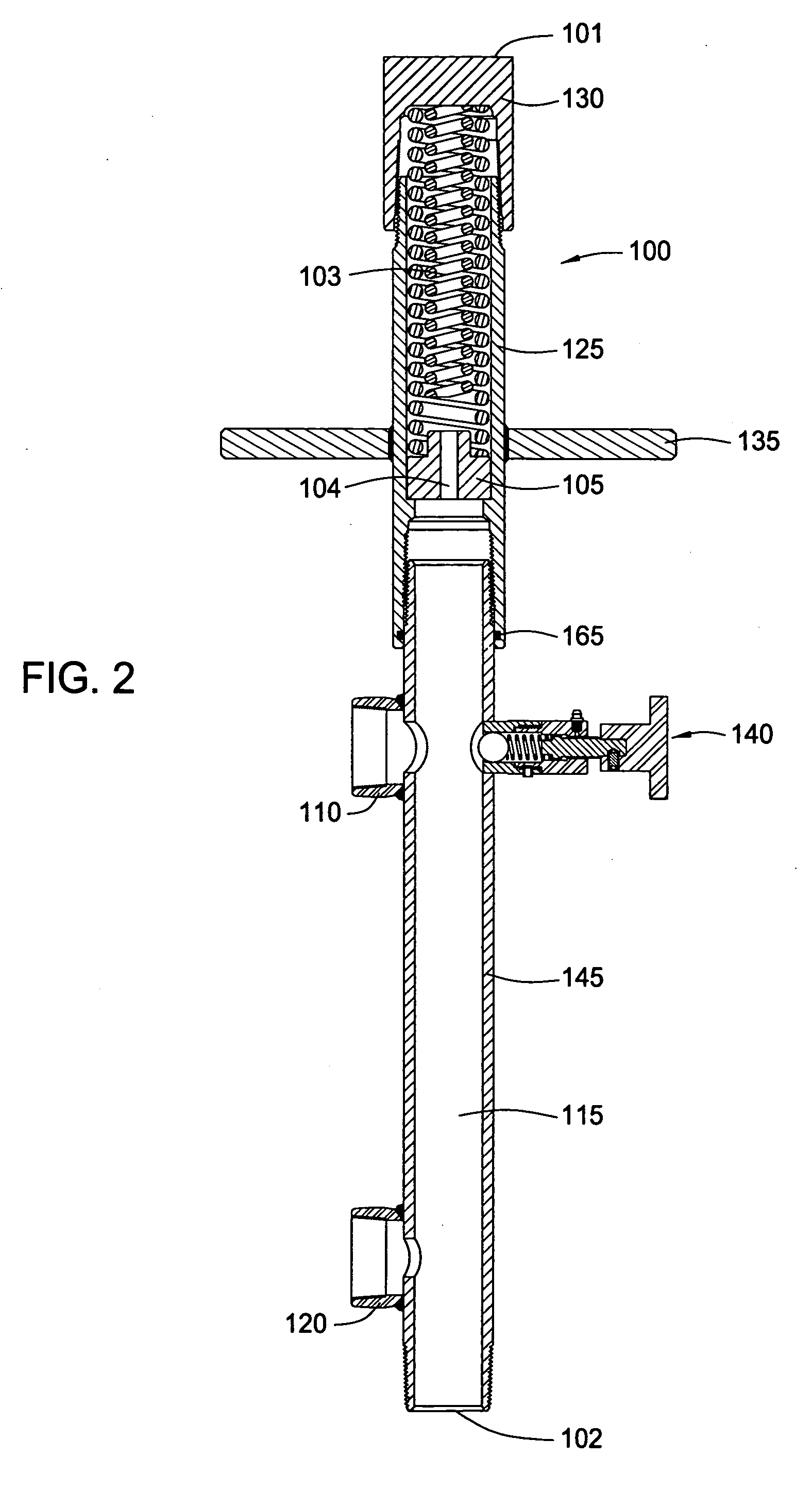
[0027] Embodiments of the present invention generally provide a lubricator capable of sufficiently cushioning a plunger of a plunger lift system when the plunger approaches and / or reaches the end of its up-stroke within the plunger lift system. Using a compressed gas chamber therein, the lubricator stops the upward force of movement of the plunger at the end of the up-stroke of the plunger without damaging the plunger, lubricator, or other internal components, and without blowing out the plunger from the lubricator. Therefore, the lubricators characteristic of embodiments of the present invention provide a safer plunger lift system which is less prone to damage. Increasing the safety of the lubricator and decreasing the damage to components of the lubricator and the plunger lift system advantageously increase the profitability of the well. The increased profitability of the well ensures because costs incurred as a result of well down-time while replacing damaged components as well a...


PUM


Abstract

Embodiments of the present invention provide methods and apparatus for reducing kinetic energy of a plunger within a plunger lift system. In one aspect, a lubricator is provided at a surface of a wellbore, the lubricator having a sealed, pressurized chamber therein to cushion the plunger upon impact. In another aspect, a method is provided for reducing the kinetic energy of the plunger by providing a compressed gas chamber within a lubricator, moving a kinetic energy-reducing surface which is partially bounding the chamber, and compressing the gas within the chamber to reduce kinetic energy of the plunger and cushion the impact force of the plunger.

Description

BACKGROUND OF THE INVENTION [0001] 1. Field of the Invention [0002] Generally, embodiments of the present invention relate to a plunger lift system for artificially lifting fluid. More specifically, embodiments of the present invention relate to a lubricator for a plunger lift system used to lift fluid from a well. [0003] 2. Description of the Related Art [0004] To obtain hydrocarbon fluid from an earth formation, a wellbore is drilled into the earth to intersect an area of interest or hydrocarbon-bearing reservoir within a formation. The wellbore may then be “completed” by inserting casing within the wellbore and setting the casing therein using cement. In the alternative, the wellbore may remain uncased (an “open hole wellbore”), or may become only partially cased. Regardless of the form of the wellbore, production tubing is typically run into the wellbore (within the casing when the well is at least partially cased) primarily to convey production fluid (e.g., hydrocarbon fluid, w...

Claims


Application Information

Patent Timeline
IPC IPC(8): E21B33/12E21B47/00E21B19/00E21B43/00E21B43/12F04B47/12
CPCE21B43/121F04B47/12
Inventor HORN, BENHEARN, WILLIAM
Owner WEATHERFORD TECH HLDG LLC
Why Eureka
Try Eureka