
A high-efficiency quick-heating type household electric water heater

A household electric water heater and fast heating technology, which is applied to water heaters, fluid heaters, lighting and heating equipment, etc., can solve the problems of slow speed and unusable heating efficiency, and achieve the effect of improving heating efficiency.

Active Publication Date: 2021-06-22
绍兴市沂风机械有限公司
View PDF16 Cites 0 Cited by
  • Summary
  • Abstract
  • Description
  • Claims
  • Application Information

AI Technical Summary

Problems solved by technology

[0005] The object of the present invention is to provide a high-efficiency instant-heating household electric water heater with high heating efficiency, fast speed and ready-to-use in order to solve the above-mentioned problems of being unable to use immediately and having low heating efficiency and slow speed.

Method used


Image

  • A high-efficiency quick-heating type household electric water heater
  • A high-efficiency quick-heating type household electric water heater
  • A high-efficiency quick-heating type household electric water heater

Examples


Embodiment 1

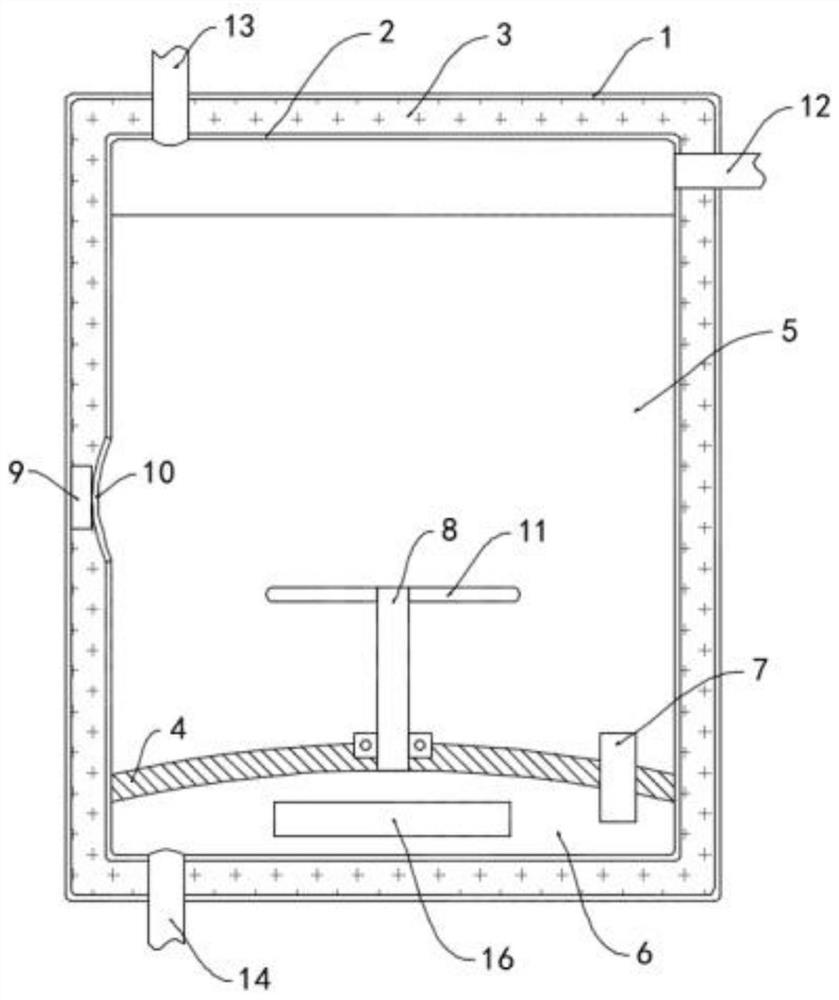
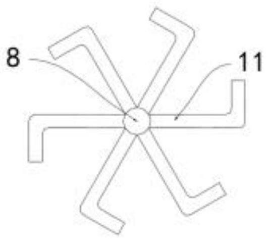
[0020] Such as Figure 1-2 As shown, a high-efficiency quick-heating household electric water heater includes an outer shell 1, an inner tank 2 is arranged inside the outer shell 1, an insulating layer 3 is filled between the inner tank 2 and the outer shell 1, and the inner wall of the inner tank 2 A partition 4 is fixedly installed on the top, and the partition 4 divides the inner tank 2 into a water storage chamber 5 and a heating chamber 6. A connecting pipe 7 is arranged vertically through the partition 4, and the volume of the heating chamber 6 is much smaller than that of the water storage chamber. The volume of the cavity 5, the side wall of the upper end of the outer casing 1 is fixedly installed with a pressure relief pipe 12, and one end of the pressure relief pipe 12 runs through the outer casing 1, the insulation layer 3 and the inner tank 2 in sequence and extends to the water storage chamber 5. Pressure relief pipe 12 is provided with a pressure valve, and the u...

Embodiment 2

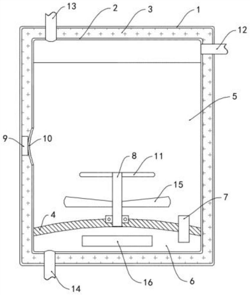
[0027] Such as image 3 As shown, the difference between this embodiment and Embodiment 1 is that the heating tube 8 is connected to the partition plate 4 in rotation, the water storage chamber 5 is provided with a horizontally arranged impeller 15, and the impeller 15 is coaxially and fixedly sleeved on the heating tube 8. In addition, the impeller 15 is located below the L-shaped branch pipe 11.

[0028] In this embodiment, the air bubble flow pushes the L-shaped branch pipe 11 to rotate, which drives the heating tube 8 and the impeller 15 to rotate. When the impeller 15 rotates, it pushes the nearby water body to flow upward, further promoting the flow and heat exchange of cold and hot water in the water storage chamber 5 , faster heating.


PUM


Abstract

The invention belongs to the field of household appliances, and in particular relates to a high-efficiency quick-heating household electric water heater, which includes an outer shell, an inner tank is arranged inside the outer shell, and an insulating layer is filled between the inner tank and the outer shell. A partition is fixedly installed on the inner wall of the inner tank, and the partition divides the inner tank into a water storage chamber and a heating chamber. A connecting pipe vertically penetrates through the connecting pipe, and the volume of the heating chamber is much larger than that of the heating chamber. Smaller than the volume of the water storage chamber, a heating rod is fixedly installed on the side wall of the heating chamber, a piezoresistor is fixedly mounted on the inner side wall of the outer shell, and a piezoresistor is fixedly mounted on the side wall of the inner tank at the position of the piezoresistor. There is a flexible board, and the heating rod is electrically connected to an external power supply through a piezoresistor. A vertical heating tube is arranged in the heating chamber, and the upper end of the heating tube penetrates the partition and extends to the water storage chamber. The present invention can quickly and uniformly heat the water in each area in the water storage chamber through high-pressure steam, and has high heating speed and high efficiency.

Description

technical field [0001] The invention belongs to the field of household electrical appliances, in particular to a high-efficiency quick-heating type household electric water heater. Background technique [0002] Water heaters are one of the household appliances commonly used in people's lives. Water heaters are divided into electric water heaters, solar water heaters and gas water heaters. Among them, electric water heaters are favored by the public because of their beautiful appearance, compact structure, simple pipelines, and safe use. [0003] Existing electric water heaters use electric energy to heat the water in the water storage tank. Before use, the heating pipe of the water heater needs to be opened in advance to heat the water to a suitable temperature, which cannot be used immediately after turning on, and the heating pipe has a negative impact on the water in the water tank. The local water body area is heated, and the heat spreads to the entire water body by conv...

Claims


Application Information

Patent Timeline
Patent Type & Authority Patents(China)
IPC IPC(8): F24H1/20F24H9/18F22B1/28F22B37/02
CPCF22B1/28F22B37/02F24H1/208F24H9/18
Inventor 刘倩倩刘红亮
Owner 绍兴市沂风机械有限公司
Learn More