

Preliminary testing method for floor vibration comfort based on heart rate change
A preliminary test and heart rate change technology, applied in the field of testing floor comfort, can solve problems affecting work and life, achieve the effects of reducing evaluation costs, comprehensively utilizing resources, and implementing quickly
- Summary
- Abstract
- Description
- Claims
- Application Information
AI Technical Summary
Problems solved by technology
Method used
Image

Examples
Embodiment 1
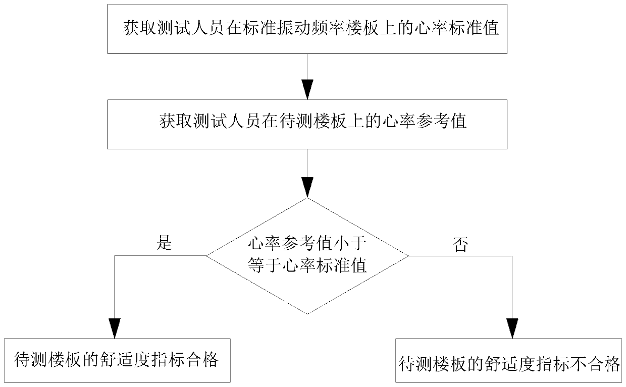
[0046] A preliminary test method for floor vibration comfort based on heart rate variation, such as figure 1 shown, including the following steps:
[0047] S1. Obtain the standard heart rate value of the tester on the standard vibration frequency floor. The heart rate standard value is used to reflect the comfort level of the tester brought by the standard vibration frequency floor. The standard vibration frequency of the floor can be 3Hz, or 4Hz, 8Hz, 10Hz, 15Hz. In this embodiment, the standard vibration frequency of the floor is 3 Hz. The age of the tester is 18 to 50 years old, the weight of the tester is 45kg to 70kg, and the height is 150cm to 180cm. The specific steps are as follows:
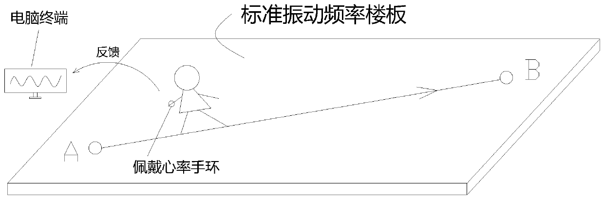
[0048] like figure 2 As shown, design a floor with the natural frequency as the critical value, the boundary condition is rigid connection around, and the working condition X1 is set: ordinary people walk from point A to point B along the span direction of the floor at a walking frequ...
Embodiment 2
[0059] On the basis of Embodiment 1, the heart rate standard value in step S1 can also be:
[0060]
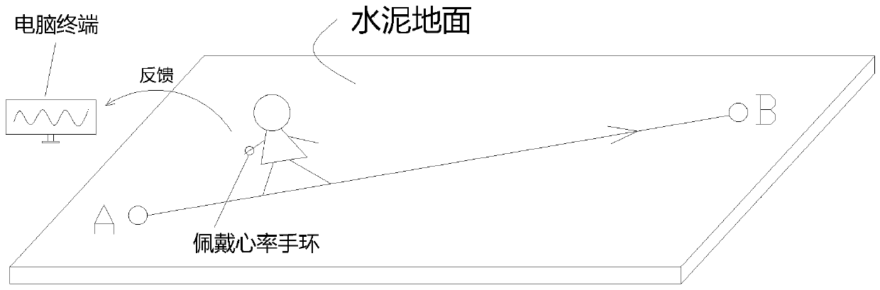
[0061] in, n is the total number of tests, in the present embodiment, the value of n is 10, z ij is the peak heart rate of the tester at the step frequency i on the concrete floor in the jth test, Y i is the peak heart rate of the tester at the step frequency i on the standard vibration frequency floor, for Absolute value of K i is the heart rate standard value at the stride i, and the stride i is i steps taken per unit time.
[0062] The heart rate reference value obtained in step S2 may also be:
[0063]
[0064] the y i is the peak heart rate of the tester at the step frequency i on the floor to be tested, for absolute value of k i is the heart rate reference value at the pace i.
PUM
| Property | Measurement | Unit |
|---|---|---|
| Weight | aaaaa | aaaaa |
Abstract
Description
Claims
Application Information