Base of prism driving device

A driving device and prism technology, used in installation, optics, instruments, etc., can solve the problems of uneven driving, difficult assembly, and difficult driving of the prism, and achieve the effect of simplifying the automatic installation process, strong overall reliability, and easy to manufacture and process.

Pending Publication Date: 2020-05-19
HENAN HAOZE ELECTRONICS
View PDF0 Cites 2 Cited by
  • Summary
  • Abstract
  • Description
  • Claims
  • Application Information

AI Technical Summary

Problems solved by technology

As a relatively advanced device, the spring-type prism motor is more and more favored by consumers and machine manufacturers in the market. However, the spring-type prism motor on the existing market is a single-axis rotation, which involves too many parts and complicated installation process. Difficult to assemble Low yield rate and poor reliability
In addition, the current prism project is still driven by electromagnetic technology. Due to the large size and mass of the prism, coupled with the potential energy of the reed, it is difficult to drive the ordinary magnet + coil scheme, and because the power produced by the current electromagnetic field and the power of the reed The potential energy is not in a balanced ratio, and there will be hysteresis when driving, which will lead to problems such as unsmooth driving of the prism

Method used


Image

  • Base of prism driving device
  • Base of prism driving device
  • Base of prism driving device

Examples


Embodiment Construction

[0025] Preferred embodiments of the present invention will be described in detail below with reference to the accompanying drawings, so as to better understand the purpose, features and advantages of the present invention. It should be understood that the embodiments shown in the drawings are not intended to limit the scope of the present invention, but only to illustrate the essence of the technical solutions of the present invention.

[0026] In the following description, for the purposes of explaining the various disclosed embodiments, certain specific details are set forth in order to provide a thorough understanding of the various disclosed embodiments. One skilled in the relevant art will recognize, however, that an embodiment may be practiced without one or more of these specific details. In other instances, well-known devices, structures and techniques associated with the present application may not have been shown or described in detail in order to avoid unnecessarily...


PUM


Abstract

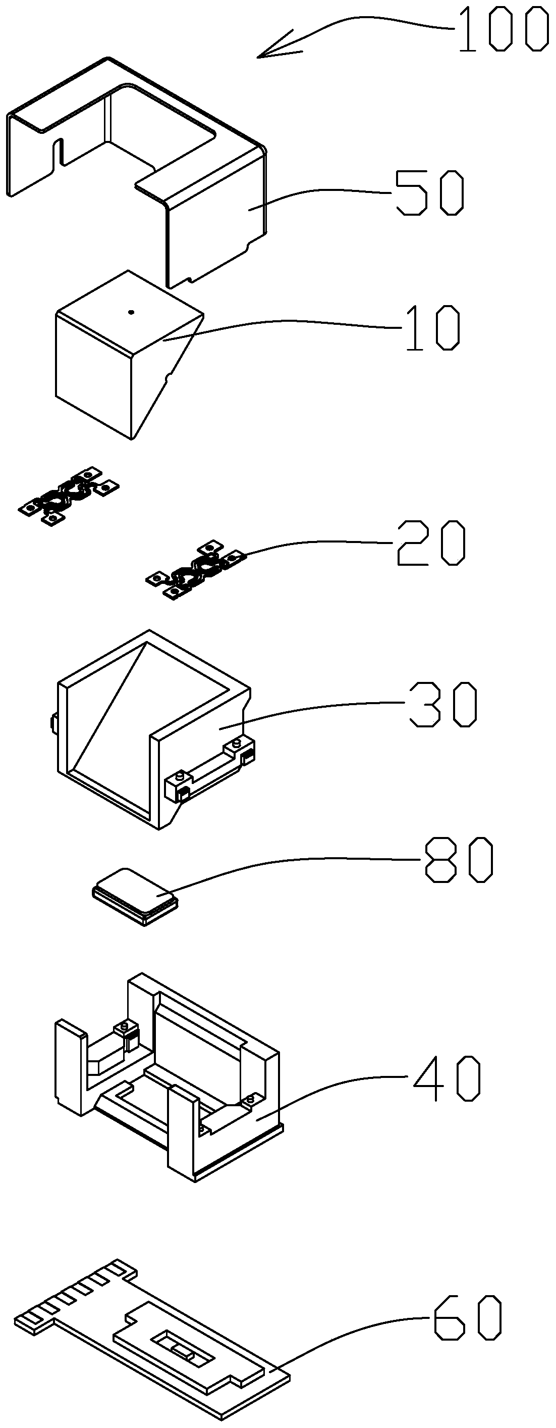
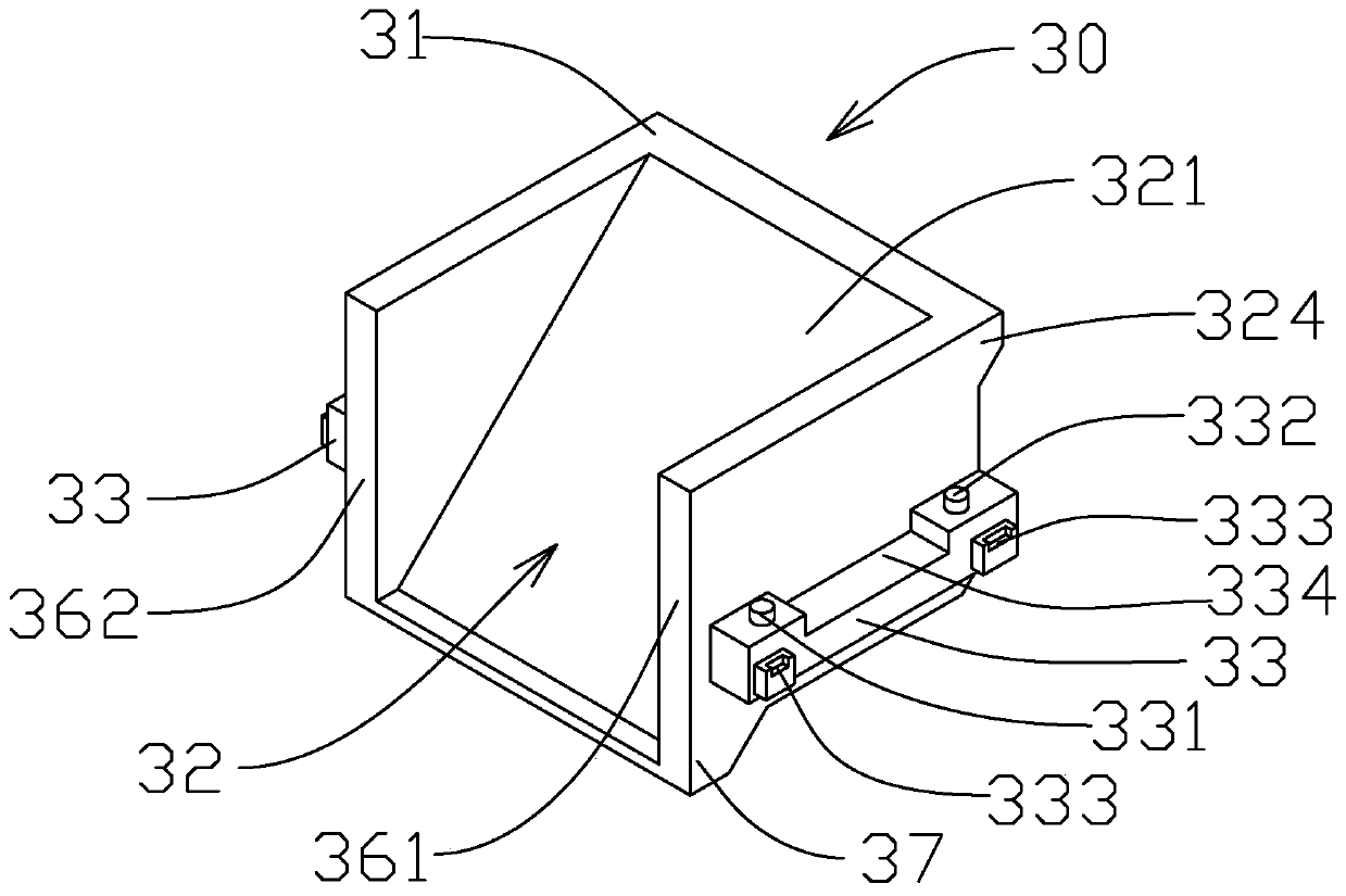
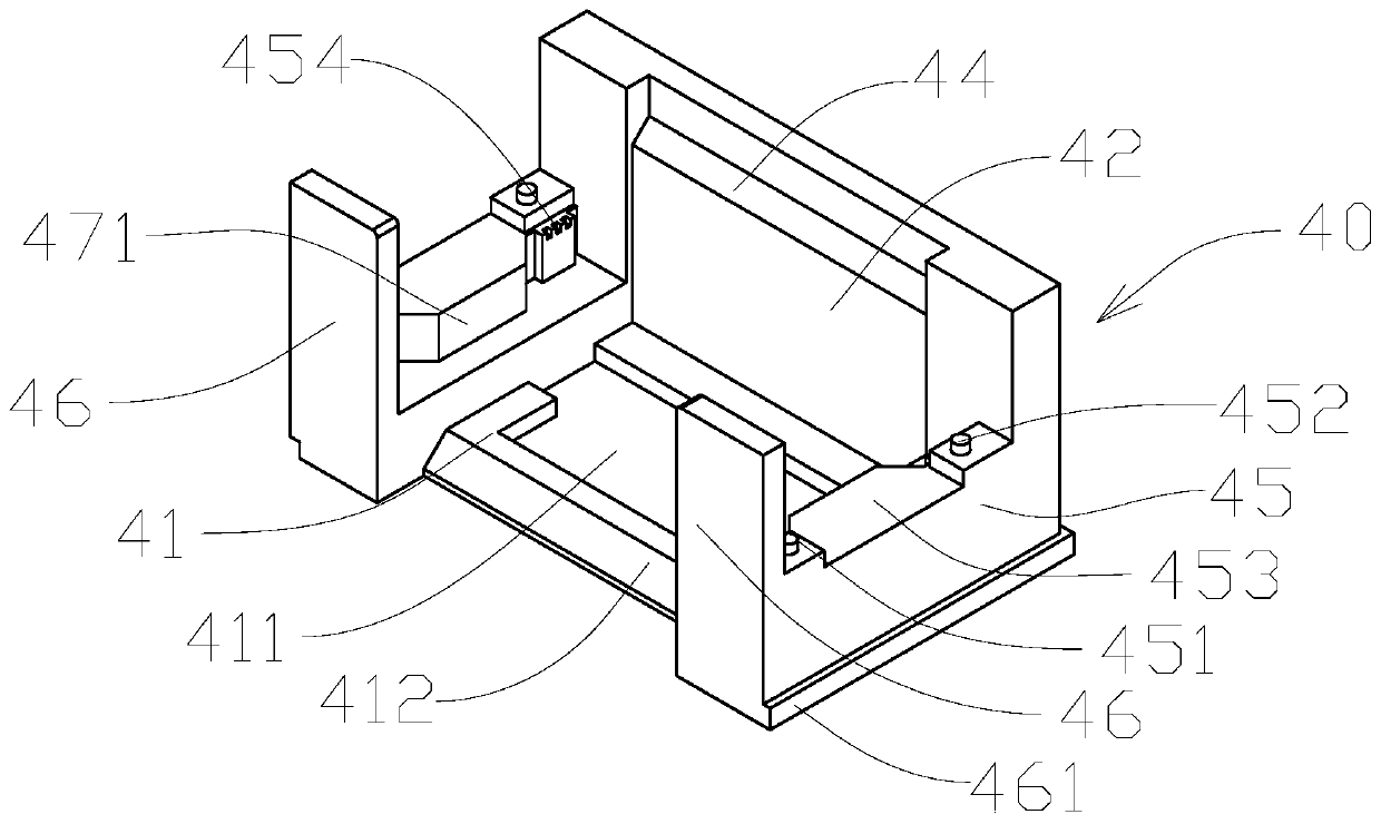
The invention discloses a base of a prism driving device, which comprises a bottom part and a rear part which are integrally formed, and the bottom part is provided with a bottom coil avoiding grooveand a bottom carrier avoiding groove. The bottom coil avoiding groove is matched with a bottom coil on a circuit board of the prism driving device; the bottom carrier avoiding groove is matched with alower convex part of a carrier of the prism driving device; the two ends of the bottom integrally extend out of a base reed installation part upwards, the upper surface of the base reed installationpart is parallel to the bottom and provided with two protrusions matched with a reed of the prism driving device, and a base damping rubber groove is formed in the inner side of the base reed installation part. The base is convenient to manufacture and machine, hysteresis generated in the driving process is optimized by adopting the damping rubber groove, magnetic force generated by the magnet isstrengthened, and a magnetic field is structured.

Description

technical field [0001] The invention relates to the technical field of optical imaging equipment, in particular to a base of a prism driving device. Background technique [0002] With the development of technology, many electronic devices (such as smart phones or digital cameras) now have the function of taking photos or recording videos. The use of these electronic devices is becoming more and more common, and they are developing towards the direction of convenience and thinner design, so as to provide users with more choices. As a relatively advanced device, the spring-type prism motor is more and more favored by consumers and machine manufacturers in the market. However, the spring-type prism motor on the existing market is a single-axis rotation, which involves too many parts and complicated installation process. Difficult assembly, low yield and poor reliability. In addition, the current prism project is still driven by electromagnetic technology. Due to the large siz...

Claims


Application Information

Patent Timeline
Patent Type & Authority Applications(China)
IPC IPC(8): G02B7/18G03B30/00
CPCG02B7/1805
Inventor 林聪彭坤刘富泉其他发明人请求不公开姓名
Owner HENAN HAOZE ELECTRONICS
Why Eureka
Try Eureka