
Circuit breaker single-coil permanent magnet operating mechanism

A permanent magnet operating mechanism, single-coil technology, applied in the direction of protection switch operation/release mechanism, etc., can solve the problems such as the contact is prone to violent collision, the current required for opening and closing is large, and the service life is affected, so as to avoid demagnetization, The effect of prolonging service life and reducing severe shock

Pending Publication Date: 2020-05-19
CHANGZHOU INST OF MECHATRONIC TECH
View PDF0 Cites 0 Cited by
  • Summary
  • Abstract
  • Description
  • Claims
  • Application Information

AI Technical Summary

Problems solved by technology

However, the ordinary single-coil monostable structure can only pass current into one coil, and a reverse magnetic field will be generated when the reverse current is passed in. The permanent magnet will be demagnetized if it is in the reverse magnetic field for a long time, which will affect the service life; at the same time, it will open and close Large current required, high energy consumption
Ordinary double-coil structure accelerates when opening and closing, and the contacts are prone to violent collisions

Method used


Image

  • Circuit breaker single-coil permanent magnet operating mechanism
  • Circuit breaker single-coil permanent magnet operating mechanism
  • Circuit breaker single-coil permanent magnet operating mechanism

Examples


Embodiment Construction

[0016] In order to make the content of the present invention more clearly understood, the present invention will be further described in detail below based on specific embodiments and in conjunction with the accompanying drawings.

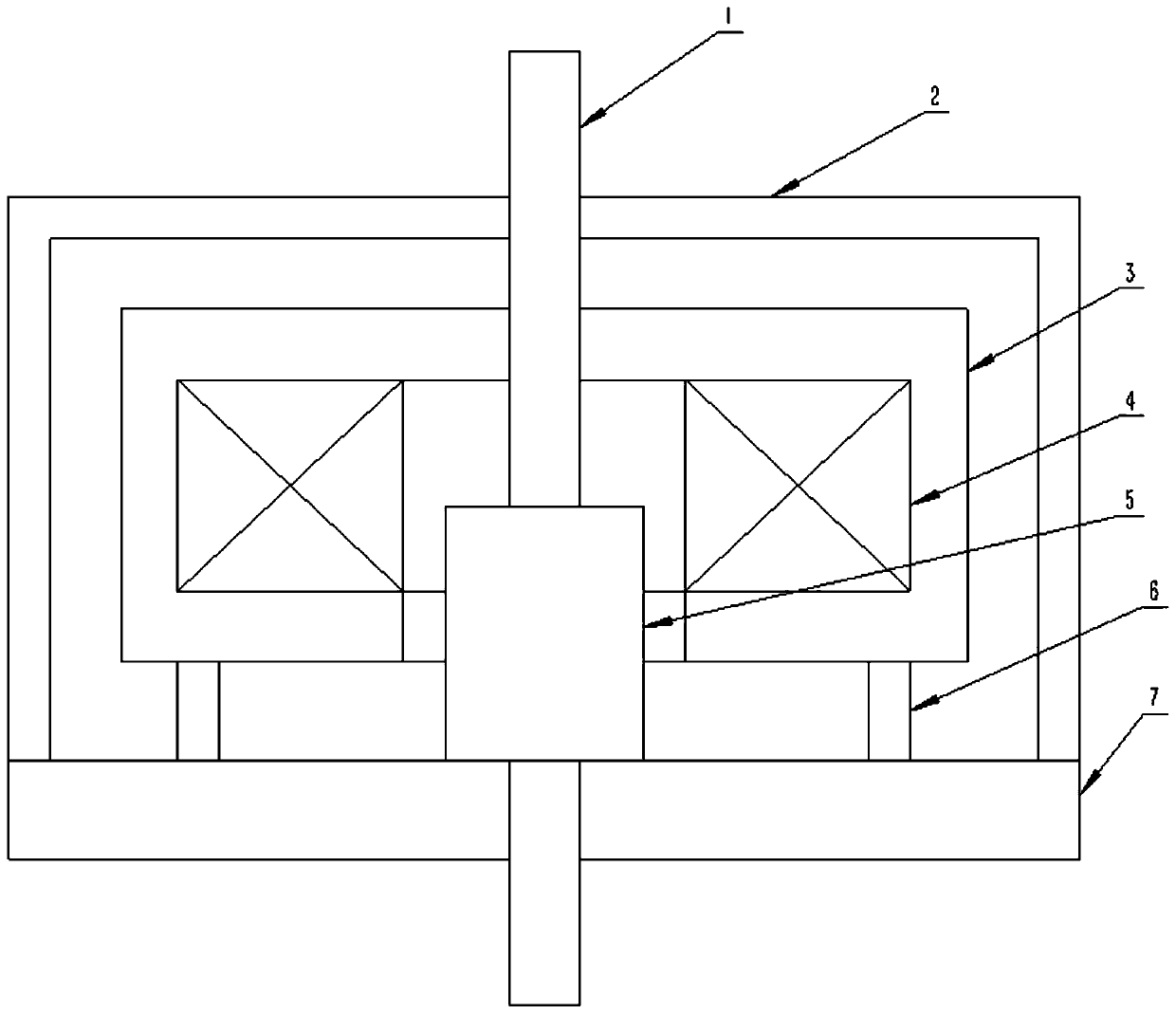
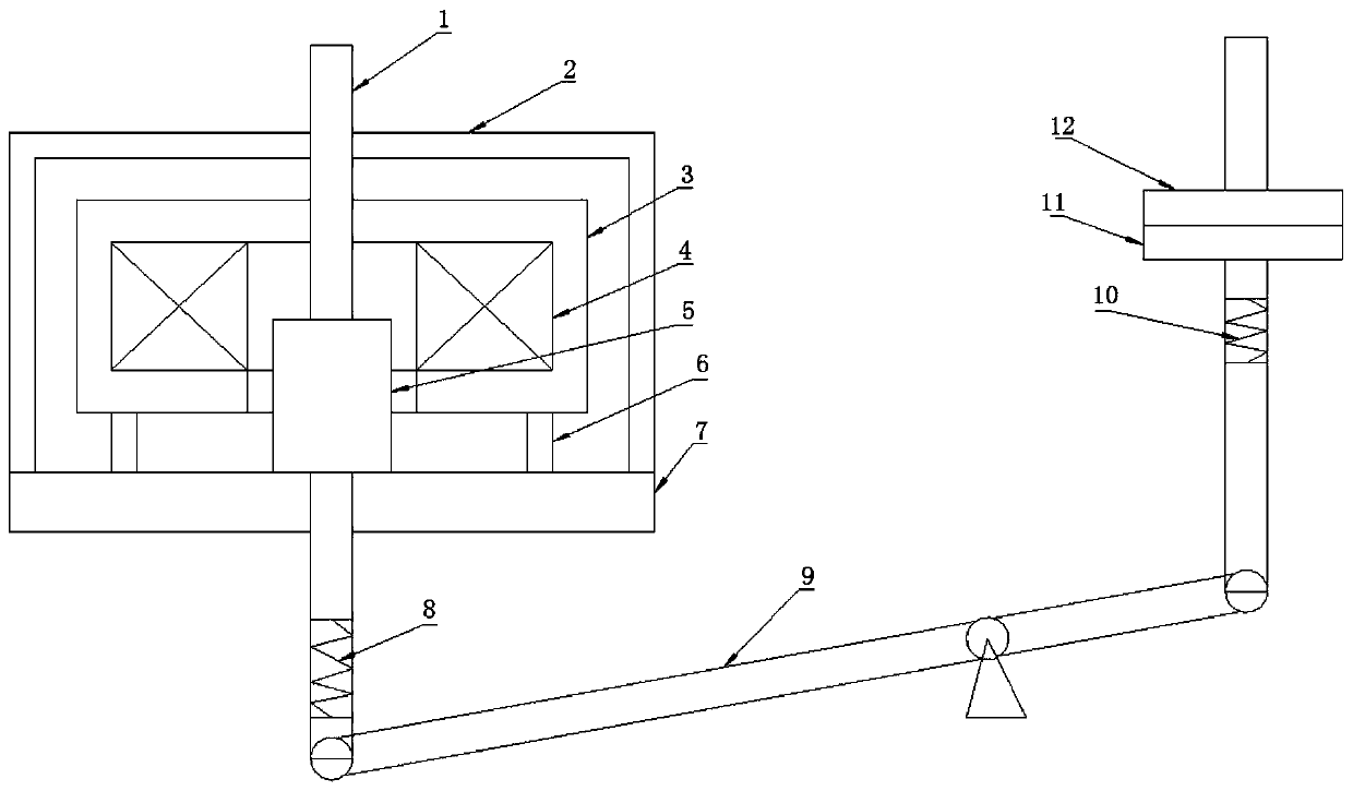
[0017] like Figure 1~3 As shown, a circuit breaker single-coil permanent magnet operating mechanism, which includes a driving mechanism and a transmission mechanism,

[0018] The driving mechanism includes a housing 2, a lower base plate 7, a fixed frame 6, a movable shaft 1, a permanent magnet 5 and a static iron core 3, the housing 2 is fixed above the lower base plate 7, the movable shaft 1 runs through the housing 2, and the permanent magnet 5 is fixed on the movable shaft 1, the shape of the permanent magnet 5 is cylindrical, the permanent magnet 5 is sleeved on the outer periphery of the movable shaft 1 and fixed by glue, the permanent magnet 5 moves together with the movable shaft 1 during the opening and closing process . The lower botto...


PUM


Abstract

The invention discloses a circuit breaker single-coil permanent magnet operating mechanism, which comprises a driving mechanism and a transmission mechanism. The driving mechanism comprises a housing,a lower bottom plate, a fixing frame, a movable shaft, a permanent magnet and a static iron core. The housing is fixed on the lower bottom plate; the movable shaft penetrates through the housing; thepermanent magnet is fixed on the movable shaft; the fixing frame is arranged on the lower bottom plate; the static iron core is fixed on the fixing frame; a coil used for being connected with an external control circuit is wound on the static iron core; the movable shaft penetrates through the center of the static iron core; and the permanent magnet, the coil, the static iron core and the coil are sequentially arranged outwards with the movable shaft as the center. The transmission mechanism comprises a buffer device and a lever, wherein the long end of the lever is connected with the bottomof the movable shaft through the buffer device, and the short end of the lever is used for being connected with an arc extinguishing chamber. The provided circuit breaker single-coil permanent magnetoperating mechanism is low in energy consumption, long in service life, small in impact, and safe and reliable.

Description

technical field [0001] The invention relates to a circuit breaker single-coil permanent magnet operating mechanism, which belongs to the technical field of circuit breakers. Background technique [0002] At present, a stable and good power control system can more effectively promote the rapid development of the social electronic information age. To ensure the smooth operation of power distribution lines and electrical equipment, circuit breakers with good performance must be equipped. As the weakest link in the circuit breaker components, the operating mechanism accounts for about 80% of the total failure rate of the circuit breaker during its operation. [0003] Among the operating mechanisms, the permanent magnet operating mechanism is currently the most commonly used, and it can be divided into three types: single-coil monostable, double-coil monostable and double-coil bistable. However, the ordinary single-coil monostable structure can only pass current into one coil, a...

Claims


Application Information

Patent Timeline
IPC IPC(8): H01H71/32H01H71/68
CPCH01H71/32H01H71/68
Inventor 马仕麟白颖王青莫莉萍赵红顺
Owner CHANGZHOU INST OF MECHATRONIC TECH
Learn More