Differential signal sampling circuit and differential signal sampling method and device

A differential signal and sampling circuit technology, applied in differential amplifiers, amplifiers with semiconductor devices/discharge tubes, electrical components, etc., can solve problems affecting output errors

Pending Publication Date: 2022-06-17
STELIGHT INSTR CO LTD
View PDF5 Cites 0 Cited by
  • Summary
  • Abstract
  • Description
  • Claims
  • Application Information

AI Technical Summary

Problems solved by technology

When the existing operational amplifier is used to amplify and sample a pair of differential signals, only this group of differential signals needs to be amplified, but affected by the precision of the resista

Method used


Image

  • Differential signal sampling circuit and differential signal sampling method and device
  • Differential signal sampling circuit and differential signal sampling method and device
  • Differential signal sampling circuit and differential signal sampling method and device

Examples


Example Embodiment

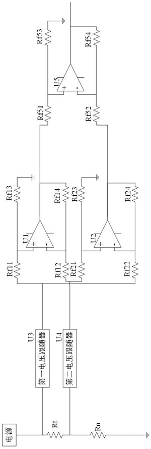
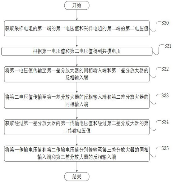
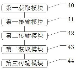
[0037] The technical solutions in the embodiments of the present application will be clearly and completely described below with reference to the drawings in the embodiments of the present application. Obviously, the described embodiments are only a part of the embodiments of the present application, but not all of the embodiments. All other embodiments obtained by those of ordinary skill in the art based on the embodiments in the present application without creative work fall within the protection scope of the present application.

[0038] The core of the present application is to provide a differential signal sampling circuit, a differential signal sampling method and device, which can reduce the serious influence of the common mode voltage amplified by the operational amplifier on the output error.

[0039] In order to make those skilled in the art better understand the solution of the present application, the present application will be further described in detail below wit...


PUM


Abstract

The invention discloses a differential signal sampling circuit and a differential signal sampling method and device, and relates to the technical field of sampling circuits. The circuit comprises a sampling resistor, a first differential amplifier, a second differential amplifier and a third differential amplifier. The voltage value of the first end of the sampling resistor and the voltage value of the second end of the sampling resistor are used as a pair of differential signals. A first differential amplifier and a second differential amplifier which are connected in a positive-negative cross mode are input, two differential voltage signals which are opposite in polarity and equal to a common-mode voltage value are obtained, and at the moment, the common-mode voltage of output signals of the first differential amplifier and the second differential amplifier is 0. Therefore, the serious influence of the common-mode voltage amplified by the operational amplifier on the output error is reduced.

Description

technical field [0001] The present application relates to the technical field of sampling circuits, and in particular, to a differential signal sampling circuit, a method and device for sampling differential signals. Background technique [0002] With the rapid development of society, the development of control circuits is also increasingly strengthened. Most circuits involving voltage and / or current are applied to sampling circuits. When the existing operational amplifier is used to amplify and sample a pair of differential signals, it is only necessary to amplify this group of differential signals, but it is affected by the resistance accuracy in the circuit and the temperature drift of the resistance during operation. The mode voltage is also amplified, and the amplified common mode voltage seriously affects the output error of the sampling. [0003] In view of the above-mentioned problems, it is a problem that those skilled in the art try to solve how to reduce the sam...

Claims


Application Information

Patent Timeline
IPC IPC(8): H03M1/12H03F1/30H03F3/45
CPCH03M1/1245H03F1/30H03F3/45928H03F2203/45051
Inventor 徐立潘朝松廉哲
Owner STELIGHT INSTR CO LTD
Why Eureka
Try Eureka