An electromagnetic vibration energy harvesting device for marine robots

An electromagnetic vibration and energy harvesting technology, applied in electromechanical devices, ocean energy power generation, machines/engines, etc., can solve the problems of departure from the actual sea wave frequency, limited energy collection efficiency, and inability to collect energy, achieving low noise, Small impact, symmetrical shape

Active Publication Date: 2021-01-01
ZHEJIANG UNIV
View PDF9 Cites 2 Cited by
  • Summary
  • Abstract
  • Description
  • Claims
  • Application Information

AI Technical Summary

Problems solved by technology

Among them, the structure of the resonant power generation device is the simplest, usually the direction of motion is a straight line, and the design is easy, but this also leads to the fact that the power generation device can only collect energy in one direction of the straight line to generate power, the power generation efficiency is low, and the maximum The frequency requirement of power generation efficiency is separated from the actual sea wave frequency; although another type of rotary power generation device has more energy collection in the direction of rotation, it cannot collect energy in the other direction
All in all, the two types of energy harvesters cannot collect energy in multiple directions when the marine robot moves irregularly, and the energy collection efficiency is limited

Method used


Image

  • An electromagnetic vibration energy harvesting device for marine robots
  • An electromagnetic vibration energy harvesting device for marine robots
  • An electromagnetic vibration energy harvesting device for marine robots

Examples


Embodiment

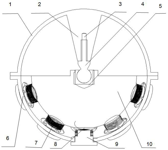
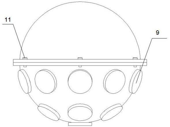
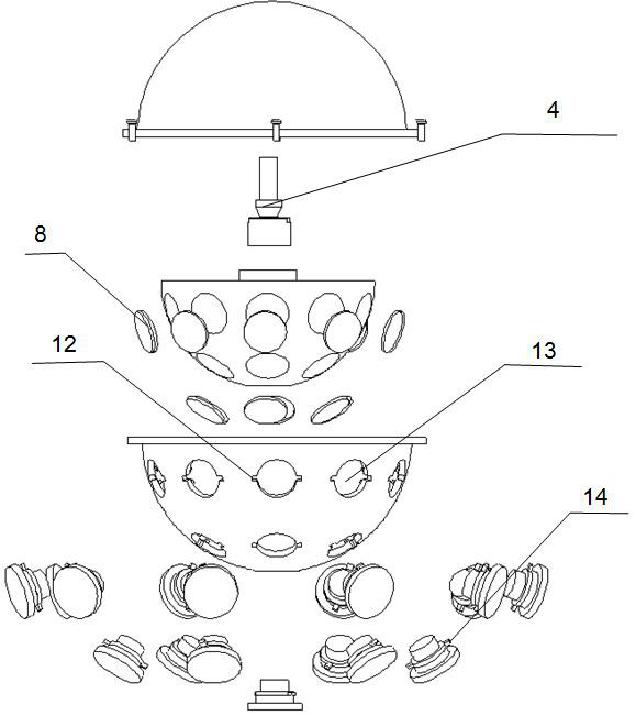
[0022]Figure 1 ~ Figure 3An electromagnetic vibration energy harvesting device is presented.

[0023]The device in the embodiment includes an upper shell 1, which is closely connected to the lower shell 6 by six screws 11, and the upper shell 1 and the lower shell 6 overlap to form a complete spherical shell. The upper shell 1 has a support column 2, and the axis of the support column 2 overlaps with the axis of the upper shell 1.

[0024]The support column 2 and the TBS joint bearing 4 are connected through a threaded hole 3, and the TBS joint bearing 4 and the hemisphere 10 are connected through a threaded hole 5. The hemisphere 10 is made of a metal material, preferably an iron alloy, on which a number of permanent magnets 8 for power generation are distributed. The sphere 10 can rotate in all directions around the center of the sphere.

[0025]Several coil column holes 13 are distributed on the lower shell 6. Each coil post hole 13 has two grooves 12 symmetrically distributed. The two co...


PUM


Abstract

The invention discloses an electromagnetic vibration energy collecting device for an ocean robot. The device comprises a hemispherical body. Permanent magnets are distributed on the surface of the hemispherical body; the hemispherical body is positioned in a lower hemispherical housing, and sphere centers of the two are same; round holes corresponding to the permanent magnets on the surface of thehemispherical body are distributed in the lower hemispherical housing, and coil columns are inserted into the round holes; the lower hemispherical housing and an upper hemispherical housing are connected to form a complete spherical housing; a supporting column is supported in the upper hemispherical housing towards the sphere center, and the supporting column is connected with the hemisphericalbody through a TBS knuckle bearing, so that the hemispherical body can rotate in any direction around the steel ball center of the TBS knuckle bearing; the magnetic poles of the outward parts of the adjacent permanent magnets on the hemispherical body are opposite; and the winding directions of coils wound on the adjacent coil columns are opposite. Energy of external objects in all directions canbe directly collected and converted into electric energy; and the overall structure is stable, the shape is symmetrical, and the influence on external device stability is small.

Description

Technical field[0001]The invention relates to the technical field of vibration energy harvesting, in particular to an electromagnetic energy harvesting device that converts wave energy into electrical energy.Background technique[0002]At present, marine robots have higher and higher energy requirements in their operations, and battery storage alone cannot meet the requirements of operations. At present, researchers have designed and manufactured power generation devices for marine robots. Generally speaking, these devices are divided into two categories: one is a resonance power generation device, and the other is a rotary power generation device. For the above two devices, Faraday's law of electromagnetic induction is used to generate electricity. Among them, the resonant power generation device has the simplest structure, usually the direction of movement is a straight line, and the design is easy, but this also results in the power generation device can only collect energy in one ...

Claims


Application Information

Patent Timeline
Patent Type & Authority Patents(China)
IPC IPC(8): H02K35/04F03B13/20
CPCF03B13/20H02K35/04Y02E10/30
Inventor 王滔朱江朱世强
Owner ZHEJIANG UNIV
Why Eureka
Try Eureka