Supercharge Your Innovation With Domain-Expert AI Agents!

Clean in place (CIP) heat exchange device

A technology of heat exchange device and heat exchanger, which is applied in the direction of cleaning hollow objects, cleaning methods and utensils, chemical instruments and methods, etc., can solve problems such as waste of resources, and achieve the effect of saving consumption and reducing input costs

Pending Publication Date: 2020-05-22
北京牵手果蔬饮品股份有限公司
View PDF0 Cites 0 Cited by
  • Summary
  • Abstract
  • Description
  • Claims
  • Application Information

AI Technical Summary

Problems solved by technology

If the released condensed water heat is discharged directly without being collected and utilized, it will undoubtedly be a waste of resources

Method used


Image

  • Clean in place (CIP) heat exchange device

Examples


Embodiment Construction

[0017] Various embodiments of the invention will be described in more detail below with reference to the accompanying drawings. In the various drawings, the same elements are denoted by the same or similar reference numerals. For the sake of clarity, various parts in the drawings have not been drawn to scale.

[0018] The specific implementation manners of the present invention will be further described in detail below in conjunction with the accompanying drawings and embodiments.

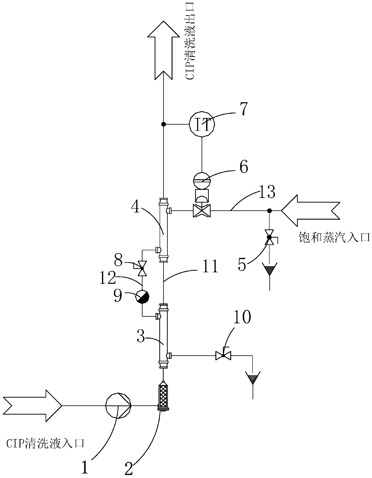
[0019] figure 1 A structural block diagram of a CIP heat exchange device provided according to an embodiment of the present invention is shown. Such as figure 1 As shown, the CIP heat exchange device includes a delivery pump 1 , a filter 2 , a condensed water heat exchanger 3 and a steam heat exchanger 4 .

[0020] Wherein, the delivery pump 1 is used to pump the CIP cleaning liquid into the condensed water heat exchanger 3 . The filter 2 is connected between the delivery pump 1 and the conden...


PUM


Abstract

The invention discloses a clean in place (CIP) heat exchange device. The CIP heat exchange device includes a condensate water heat exchanger for pre-heating CIP cleaning liquid, a first pipeline connected with the condensate water heat exchanger and used for conveying the pre-heated CIP cleaning liquid, a steam heat exchanger connected with the first pipeline and used for receiving the pre-heatedCIP cleaning liquid and heating the pre-heated CIP cleaning liquid to a preset temperature, a second pipeline connected with the steam heat exchanger and the condensate water heat exchanger separatelyand used for discharging condensate water in the steam heat exchanger to the condensate water heat exchanger and a third pipeline connected with the steam heat exchanger and used for providing saturated steam to the steam heat exchanger. The CIP heat exchange device preheats the CIP cleaning liquid through the heat energy of the saturated condensate water of the steam heat exchanger, fully utilizes the heat energy of the supplied steam, saves the amount of the steam, and reduces the input cost of production.

Description

technical field [0001] The invention relates to the field of CIP cleaning, and further relates to a CIP heat exchange device. Background technique [0002] In the pharmaceutical, printing and dyeing, and food processing industries, production equipment and pipelines will produce some sediments after use, and the sediments will remain on the pipeline walls, which will easily cause pollution and even block the pipelines. It is necessary to clean and maintain the equipment regularly. If the quality of the cleaning work However, the product quality will be seriously affected. The conventional cleaning system is off-line cleaning. When cleaning, the entire production equipment needs to be shut down first, and then the equipment to be cleaned is disassembled. After disassembly, each part is cleaned repeatedly. , until it is cleaned, and finally assemble the equipment with the cleaning feeling, and then resume production. The whole process is time-consuming and labor-intensive, was...

Claims


Application Information

Patent Timeline
IPC IPC(8): B08B9/032B08B13/00
CPCB08B9/032B08B13/00
Inventor 石均李向阳刘祥祥
Owner 北京牵手果蔬饮品股份有限公司
Features
  • R&D
  • Intellectual Property
  • Life Sciences
  • Materials
  • Tech Scout
  • Unparalleled Data Quality
  • Higher Quality Content
  • 60% Fewer Hallucinations
Learn More