
Sediment resisting butterfly valve

A sediment and butterfly valve technology, applied in the field of anti-sediment butterfly valves, can solve problems such as unfavorable use of butterfly valves, wear of valve stems and bushings, and jamming

Active Publication Date: 2020-05-22
TIANHONG VALVE TECH QUANZHOU CO LTD
View PDF9 Cites 0 Cited by
  • Summary
  • Abstract
  • Description
  • Claims
  • Application Information

AI Technical Summary

Problems solved by technology

[0004] During the use of the butterfly valve, there is inevitably a certain amount of sand in the fluid. When the butterfly valve is opened and closed, the sand easily enters the shaft sleeve from the medium gap groove between the valve seat and the valve stem. After a large amount of sand enters, it will This causes the valve stem and the shaft sleeve to be worn or even stuck, which is not conducive to the use of the butterfly valve. The protection level to prevent sediment from entering the shaft sleeve is poor, which cannot reduce the risk and provide multiple protections. The service life of the butterfly valve is short and requires maintenance. or costly to replace

Method used


Image

  • Sediment resisting butterfly valve
  • Sediment resisting butterfly valve

Examples


Embodiment Construction

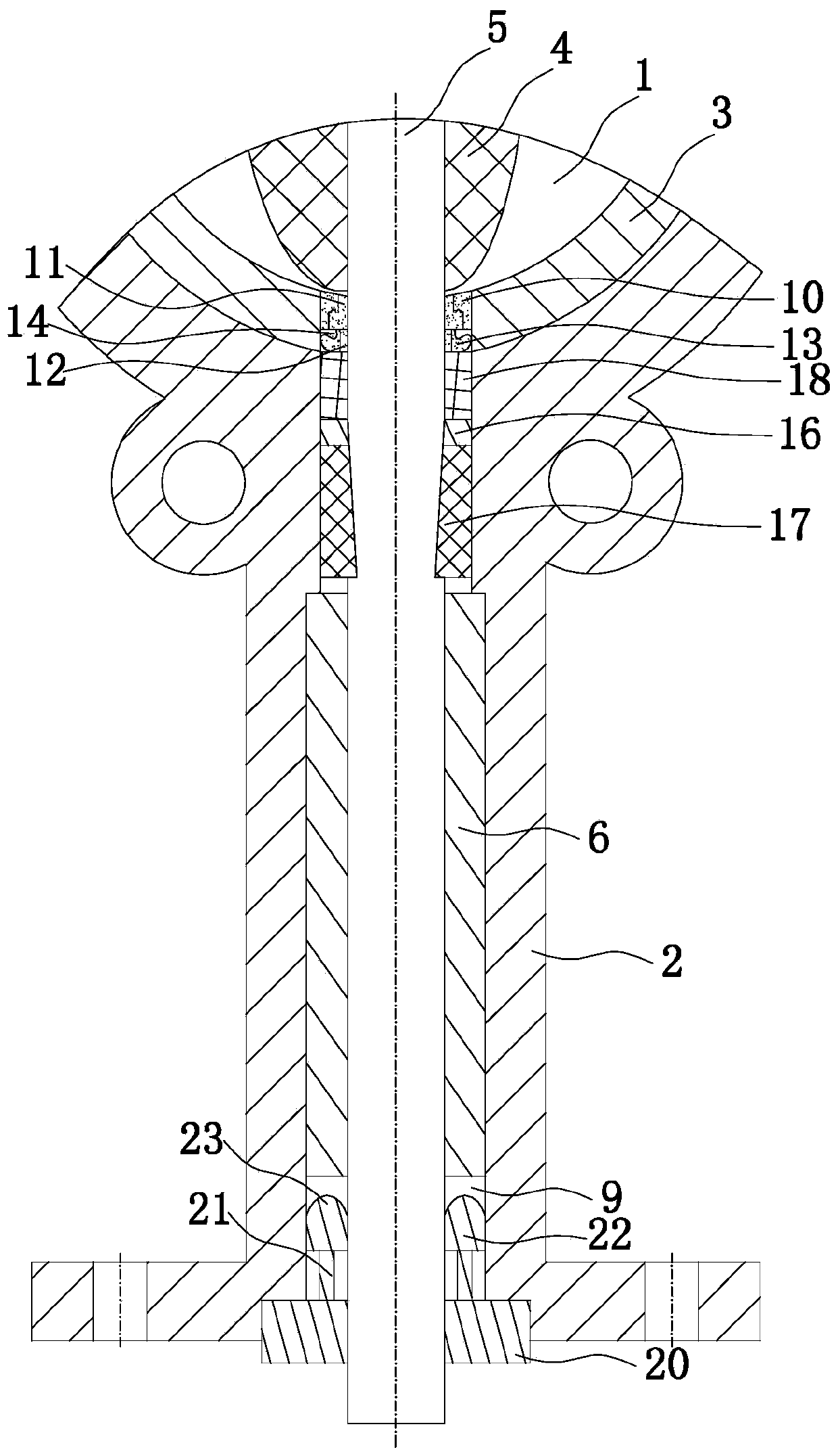
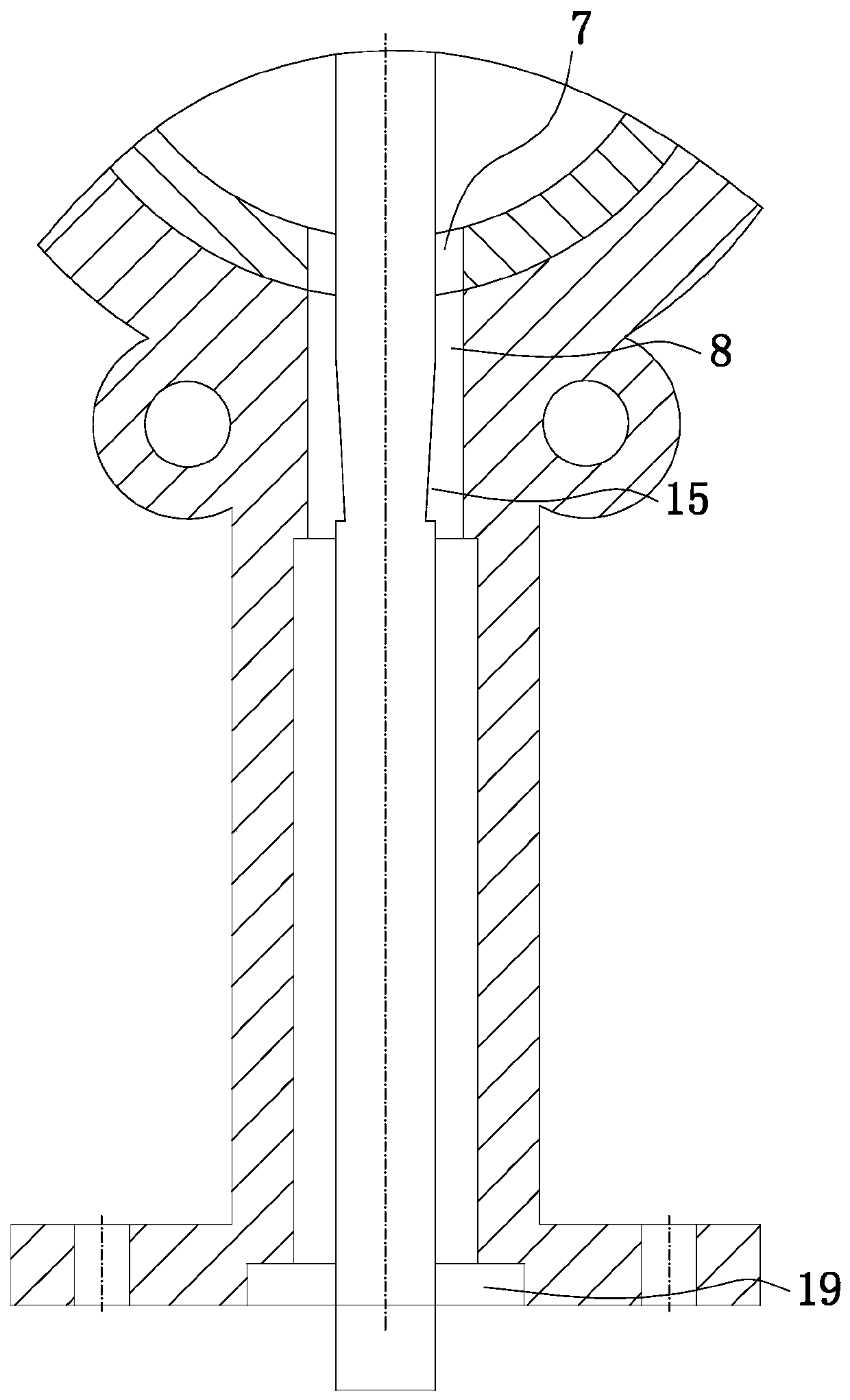
[0022] The following is a clear and complete description of the technical solution of the patent of the present invention in conjunction with the accompanying drawings. Apparently, the described embodiments are part of the embodiments of the present invention, not all of them. Based on the embodiments of the present invention, all other embodiments obtained by those skilled in the art without creative efforts fall within the protection scope of the present invention. In the case of no conflict, the features in the specific implementation manners in this application can be combined with each other.

[0023] see Figure 1 to Figure 2 As shown, the technical solution adopted in this embodiment is:

[0024]The anti-sediment butterfly valve includes a valve body 2 with a fluid passage 1, a valve seat 3 arranged on the inner wall of the fluid passage 1, and a butterfly plate that is rotatably arranged in the valve seat 3 and can be used to seal the fluid passage 1 4. The valve rod...


PUM


Abstract

The invention provides a sediment resisting butterfly valve which can prevent sediment from entering a shaft sleeve, is esxcellent in protective level, can lower the risk, play multiple protection, prolong the service life of the butterfly valve, and lower the maintaining or changing cost. The sediment resisting butterfly valve comprises a valve body, a valve seat, a butterfly plate, a valve rod,and a shaft sleeve, wherein a fluid passage is formed in the valve body; the valve seat is arranged on the inner wall of the fluid passage; the butterfly plate is rotatably arranged in the valve seatand can be used for sealing the fluid passage; the valve rod in linkage fit with the butterfly plate is rotatably arranged in the driving end of the valve body; the shaft sleeve is arranged in the driving end of the valve body and is used for connecting the valve body and the valve rod; a medium clearance groove is formed between the valve rod and the valve seat; a first fit clearance groove is formed between the valve rod and the valve body and is also formed in the side, close to the medium clearance groove, of the shaft sleeve; and a second fit clearance groove is formed in the side, far away from the medium clearance groove, of the shaft sleeve.

Description

technical field [0001] The invention relates to the technical field of valves, in particular to an anti-sediment butterfly valve. Background technique [0002] A valve is a device used to control the direction, pressure, and flow of a fluid in a fluid system. A valve is a device that makes or stops the flow of media (liquid, gas, powder) in piping and equipment and controls its flow. Specifically, it can be used to control the flow of various types of fluids such as air, water, steam, various corrosive media, mud, oil, liquid metal and radioactive media. The valve is a control component in the pipeline fluid delivery system. It is used to change the passage section and the flow direction of the medium, and has the functions of diversion, cut-off, throttling, check, diversion or overflow relief. [0003] Butterfly valve, also known as flap valve, is a regulating valve with simple structure, which can be used for switch control of low-pressure pipeline medium. of a valve. ...

Claims


Application Information

Patent Timeline
IPC IPC(8): F16K1/22F16K1/226F16K27/08F16K41/02
CPCF16K1/2268F16K1/224F16K27/08
Inventor 卓友钦洪宝山卓志坚
Owner TIANHONG VALVE TECH QUANZHOU CO LTD
Learn More