Layered direct-current power transmission system

A technology of direct current transmission system and direct current transmission line, which is applied in the direction of AC network circuit, wind power generation, electrical components, etc. It can solve the problems of poor system stability and reliability, large loss of transmission line, and difficulty in line erection, so as to improve reliability and stability, reducing the difficulty of line erection, and flexible planning and distribution

Active Publication Date: 2020-05-22
HUAZHONG UNIV OF SCI & TECH
View PDF4 Cites 0 Cited by
  • Summary
  • Abstract
  • Description
  • Claims
  • Application Information

AI Technical Summary

Problems solved by technology

[0006] 1. It is necessary to build a large-capacity voltage source converter station to facilitate access to wind power, photovoltaic power generation and other new energy power generation systems, which brings high costs and high losses;
[0007] 2. Each power station needs to be connected to the AC side of the voltage source converter station through its own long-distance AC transmission line. Since the long-distance AC transmission line will generate a large amount of reactive power, and the AC transmission line is a three-phase line, Each AC transmission line contains 3 wires, resulting in large loss of transmission lines, high cost, and difficulty in line erection;
[0008] 3. Since each power station is interconnected through AC transmission lines, any AC fault will affect all power stations, resulting in poor system stability and reliability

Method used


Image

  • Layered direct-current power transmission system
  • Layered direct-current power transmission system
  • Layered direct-current power transmission system

Examples


Embodiment Construction

[0045] In order to make the object, technical solution and advantages of the present invention clearer, the present invention will be further described in detail below in conjunction with the accompanying drawings and embodiments. It should be understood that the specific embodiments described here are only used to explain the present invention, not to limit the present invention. In addition, the technical features involved in the various embodiments of the present invention described below can be combined with each other as long as they do not constitute a conflict with each other.

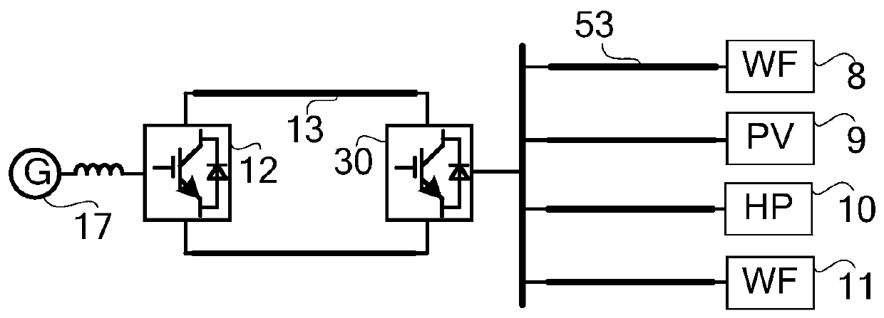
[0046] figure 1 Shown is the existing scheme of collecting multiple power stations through AC transmission lines through a centralized single high-voltage converter station. The principle is to build a single large-capacity high-voltage converter station 30, and the AC side of the high-voltage A plurality of AC transmission lines 53 are interconnected with wind power stations, photovoltaic powe...


PUM


Abstract

The invention belongs to the field of power system power transmission and distribution. The invention provides a layered direct-current power transmission system used for transmitting a large amount of renewable energy power generation distributed in different regions to a load center. The system is formed by interconnecting a high-voltage converter station and a plurality of low-voltage converterstations, and the high-voltage converter station is formed by connecting a high-end converter and a low-end converter in series. A direct-current port of the high-voltage converter station is connected to a direct-current port of the receiving-end power grid high-voltage converter station through a direct-current transmission line; the low-end converter of the high-voltage converter station is connected with the direct-current side of one or more low-voltage converter stations through a direct-current transmission line, the alternating-current side of each low-voltage converter station is connected with the alternating-current system of each low-voltage converter station, and the high-end converter of the high-voltage converter station and the alternating-current side of the low-end converter are connected to the alternating-current system where the high-voltage converter station is located. According to the topology, the geographic position of each renewable energy power station canbe arranged more conveniently, alternating current side isolation of each renewable energy power station is realized, and the total capacity of a voltage source type converter in the whole system is reduced.

Description

technical field [0001] The invention belongs to the field of electric power transmission and distribution, and in particular relates to a layered DC power transmission system, which is used to transmit power generation of a large amount of renewable energy distributed in different regions to a load center. Background technique [0002] my country is currently facing a severe smog problem. One of the main reasons for the smog problem is that our country relies too much on coal and other fossil energy sources. Vigorously developing renewable energy such as solar power, wind power, and hydropower is the solution to the smog problem in our country. fundamental measures. Northwest China has a lot of wind power and solar power resources, and Southwest China has a lot of hydropower, wind power and solar power resources. Taking the five provinces of Inner Mongolia, Xinjiang, Gansu, Qinghai and Ningxia as examples, the exploitable capacity of wind energy and photovoltaic power genera...

Claims


Application Information

Patent Timeline
Patent Type & Authority Applications(China)
IPC IPC(8): H02J3/38
CPCH02J3/381Y02E60/60
Inventor 林卫星文劲宇
Owner HUAZHONG UNIV OF SCI & TECH
Why Eureka
Try Eureka