
Floating device of paddy field operation equipment driving system

A technology of operation equipment and drive system, applied in agriculture, the chassis of agricultural machinery, agricultural machinery and machinery, etc., can solve the problems of deviation, low ground clearance, low power, etc., to avoid slippage and deviation, and to turn flexibly , the effect of increasing resistance

Inactive Publication Date: 2020-05-26
ZHEJIANG YISEN MACHINERY
View PDF5 Cites 0 Cited by
  • Summary
  • Abstract
  • Description
  • Claims
  • Application Information

AI Technical Summary

Problems solved by technology

[0004] First: the power is small, and it can no longer meet the requirements of multi-functional operations.
[0005] Second: the ground clearance is low, and it is two-wheel drive, especially when working in wet paddy fields, when encountering mud fields with different depths, it is easy to slip, run off, and turn inflexibly

Method used


Image

  • Floating device of paddy field operation equipment driving system
  • Floating device of paddy field operation equipment driving system
  • Floating device of paddy field operation equipment driving system

Examples


Embodiment 1

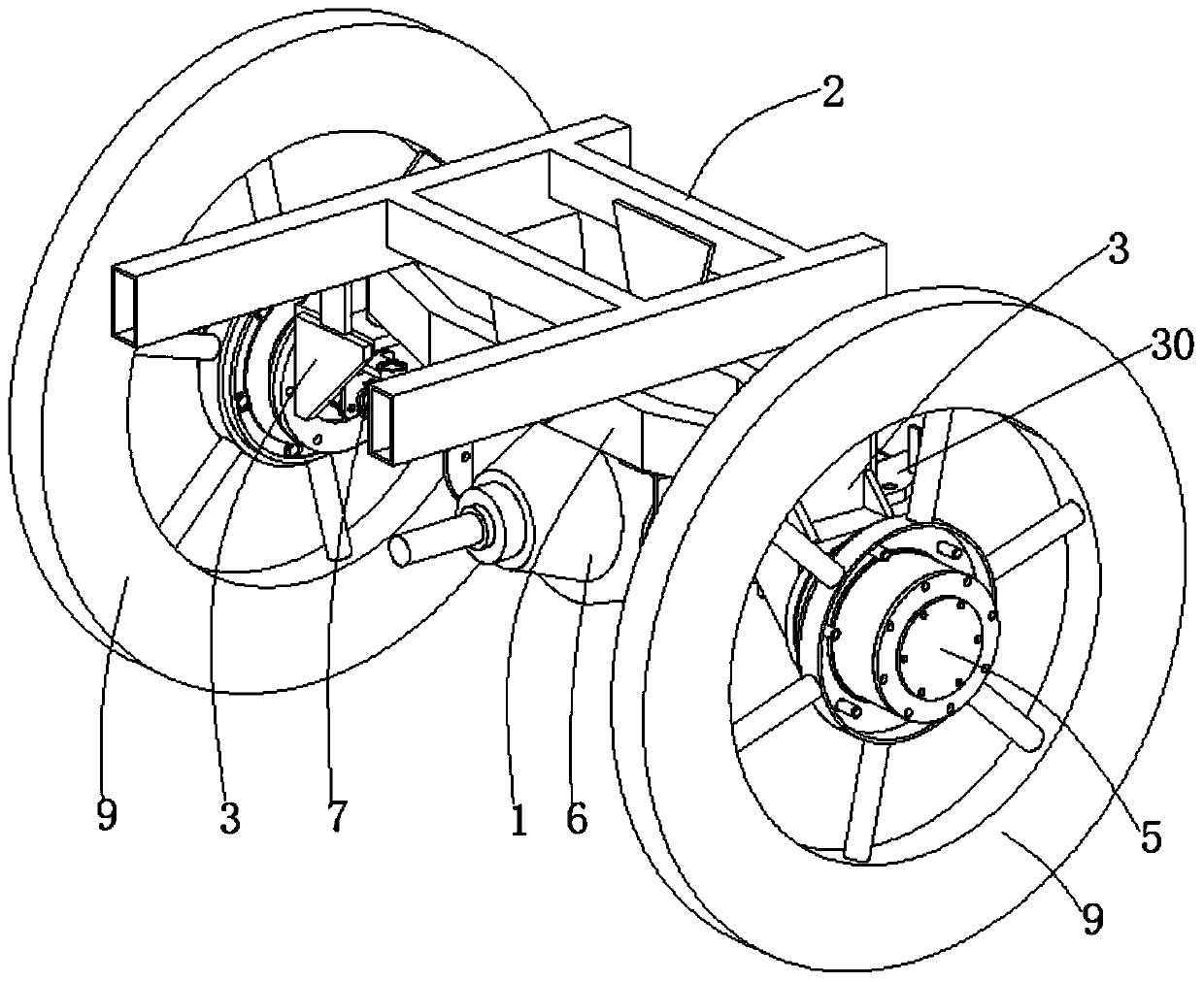
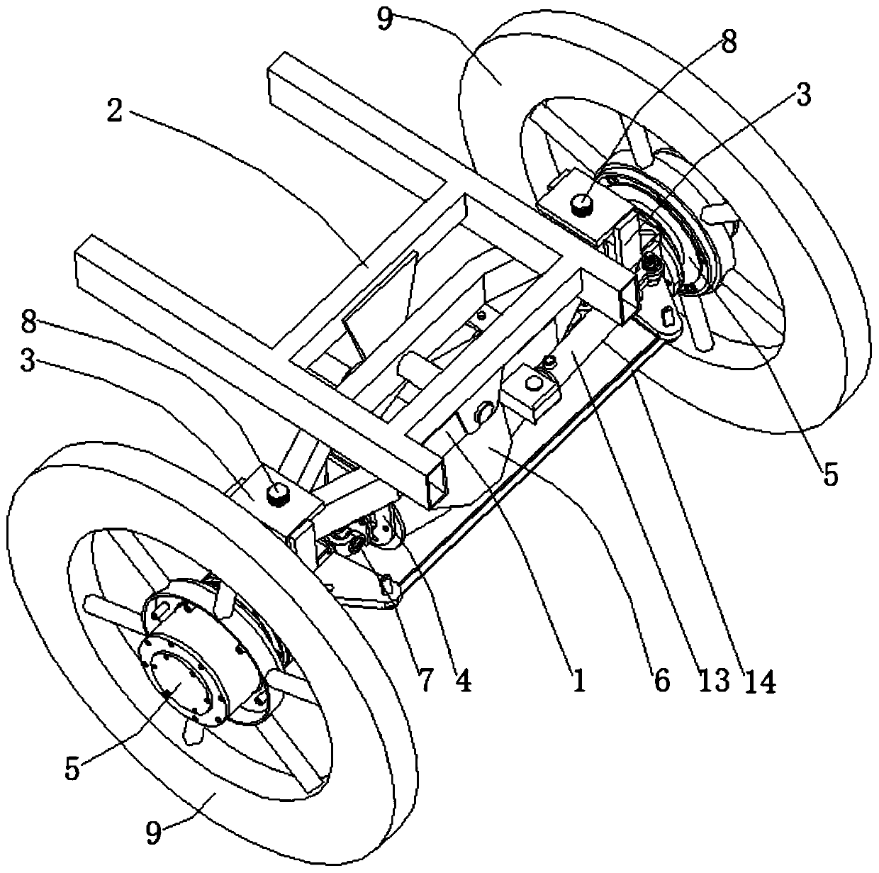
[0039] The floating device of the driving system of the paddy field operation equipment, the torque entered from the input shaft of the differential 6 passes through the differential 6 and then output from the output shaft of the differential 6, and then drives the active fork 1 70 to rotate, and the active fork 1 70 passes through the cross shaft Drive driven fork 1 71-1 rotates with external spline shaft 1 71, external spline shaft 1 71 drives internal spline shaft 1 72 to rotate, and internal spline shaft 1 72 rotates with driven fork 2 72-1, The driven fork two 72-1 drives the driven fork three 73 to rotate through the cross shaft.

[0040] Then the driven fork three 73 drives the universal joint connector 51 to rotate, and the inner spline one 51-1 of the universal joint connector 51 drives the main shaft 53 to rotate through the outer spline two 53-1, and the main shaft 53 is in the needle bearing 5 -2 internal rotation, the external spline three 53-2 at the end of the m...

Embodiment 2

[0042] On the basis of Embodiment 1, the side of the lower frame 1 is provided with a hinged seat 12, and the hinged seat 12 is hinged with a steering cylinder 13, such as Figure 5 As shown, the side wall of the wheel frame 3 is provided with a steering arm 31, the steering arm 31 is provided with an inner pin hole 31-1 and an outer pin hole 31-2, and the end of the piston rod of the steering cylinder 13 and the inner pin hole on one side 31-1 is hinged, and a steering tie rod 14 is arranged between the two outer pin holes 31-2, and a steering arm 31 is driven by the telescoping of the piston rod of the steering cylinder 13 to rotate the wheel frame 3, and the steering tie rod 14 synchronously drives the other A wheel frame 3 rotates to realize the steering operation, and the steering is stable and reliable.


PUM


Abstract

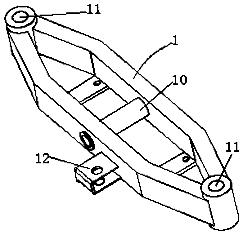
The invention discloses a floating device of a paddy field operation equipment driving system. The floating device comprises a lower framework, an upper framework, wheel frames, a hanging bracket, wheel and axle assemblies, a differential mechanism, universal shaft assemblies, main pins and rollers, wherein an axle sleeve is arranged in the middle of the lower framework; pin holes are formed in both ends of the lower framework; the upper framework is rotationally connected with the axle sleeve through a shaft; upper ends of the wheel frames are hinged with the pin holes through the main pins;the hanging bracket is connected with the lower end of the lower framework; the hanging bracket is connected with both sides of the differential mechanism in a fastened manner; wheel discs are arranged at lower ends of the wheel frames; the wheel and axle assemblies are connected with the wheel discs in a fastened manner; one ends of the universal shaft assemblies are connected with the output shaft of the differential mechanism; the other ends of the universal shaft assemblies are connected with the wheel and axle assemblies; and the rollers are connected with the wheel and axle assemblies ina fastened manner. The floating device is good in power and high in ground clearance; and in addition, as the input shaft of the differential mechanism is connected, multi-wheel driving can be achieved, and the floating device does not slip off or run off tracking and is stable in steering in rice fields with different mud depths.

Description

technical field [0001] The invention belongs to the technical field of agricultural machinery, in particular, the invention relates to a floating device of a drive system of paddy field operation equipment. Background technique [0002] With the advancement of social science and technology, agricultural modernization has been put on the agenda. In order to achieve large-scale agricultural production, the requirements for multi-functional paddy field operation machinery that can meet agronomic requirements such as transplanting, fertilizing, spraying, and sowing are getting higher and higher. [0003] The current paddy field operation equipment is commonly used in the market to use the head of the high-speed rice transplanter as the power chassis, and assemble various agricultural machinery to achieve multi-functional operations. The disadvantages of using the head of the high-speed rice transplanter are: [0004] First: the power is small, and it can no longer meet the requi...

Claims


Application Information

Patent Timeline
IPC IPC(8): A01B51/02A01B71/06
CPCA01B51/02A01B71/06
Inventor 曾联朱建平杨伟
Owner ZHEJIANG YISEN MACHINERY
Learn More