Working condition classification method

A classification method and technology of working conditions, applied in the fields of instruments, character and pattern recognition, data processing applications, etc., can solve the problems of poor extrapolation ability, model effect depends on the quality of modeling data, and lack of physical meaning of model parameters. Good extrapolation ability, improved working condition classification effect, and strong model adaptability

Pending Publication Date: 2020-05-26
QUANZHOU INST OF EQUIP MFG
View PDF3 Cites 0 Cited by
  • Summary
  • Abstract
  • Description
  • Claims
  • Application Information

AI Technical Summary

Problems solved by technology

[0005] However, the above method has at least the following defects: using the method based on data clustering, most of the data models can only be effective within a small range of working conditions, and the extrapolation ability is poor; the model effect is overly dependent on the quality of the modeling data; the model parameters are insufficient physical meaning

Method used


Image

  • Working condition classification method
  • Working condition classification method
  • Working condition classification method

Examples


Embodiment Construction

[0026] The technical solutions in the embodiments of the invention will be clearly and completely described below in conjunction with the accompanying drawings in the embodiments of the invention. Obviously, the described embodiments are only some, not all, embodiments of the invention. Based on the embodiments of the present invention, all other embodiments obtained by persons of ordinary skill in the art without making creative efforts fall within the protection scope of the present invention.

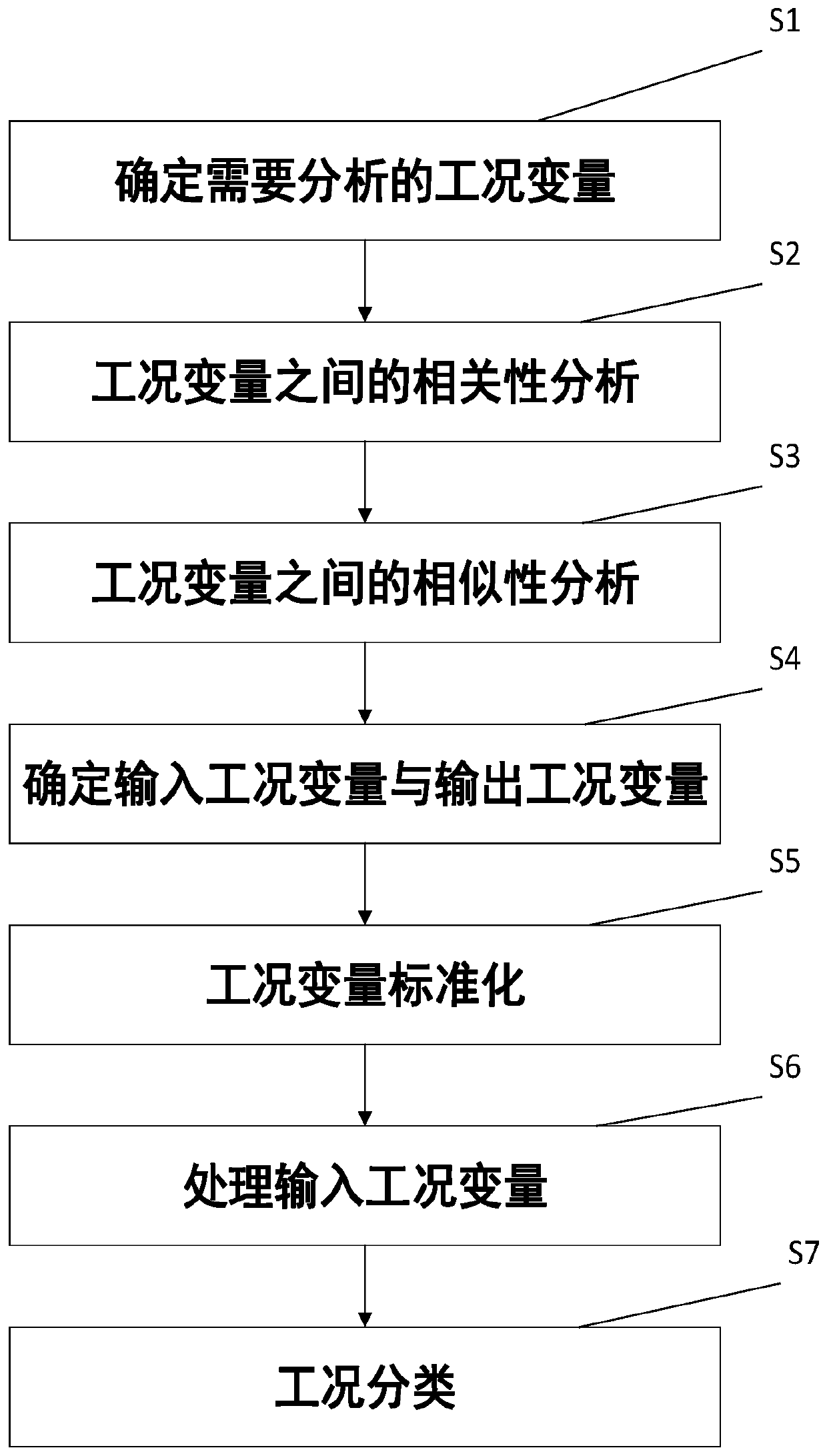
[0027] Reference manual attached figure 1 , which is applied to a group of wind turbines in a large wind farm as an example, and the method is described in detail.

[0028] S1. Determine the working condition variables to be analyzed;

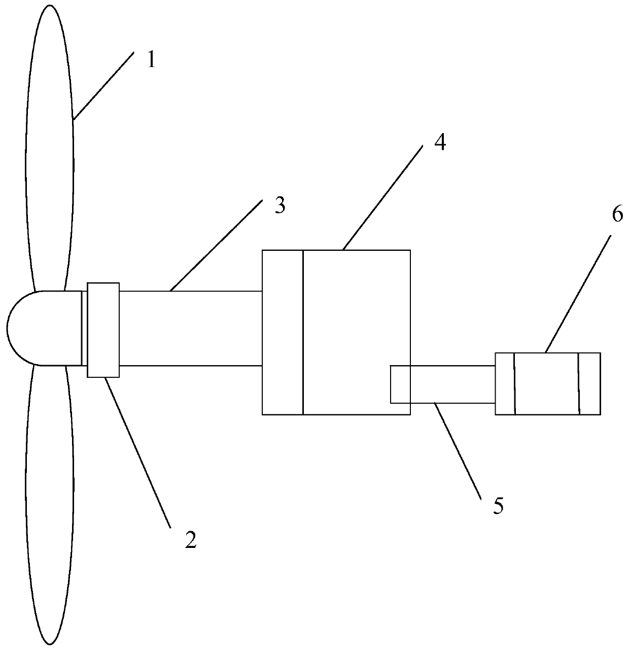
[0029] Specifically, as described in the attached figure 2 Shown is a simplified schematic diagram of a unit. The transmission chain part of the unit includes: impeller (including blades and hub), main shaft, main bearing, gearbox, coupling and gen...


PUM


Abstract

The invention discloses a working condition classification method. The method comprises the steps of determining working condition variables needing to be analyzed; analyzing correlation among the working condition variables; analyzing the similarity among the working condition variables; determining an input working condition variable and an output working condition variable; standardizing working condition variables; processing an input working condition variable; working condition classification. The method has the advantages that (1) the label-free working condition classification effect can be improved; and (2) the method has good extrapolation capability and strong model adaptability; and (3) nonlinear characteristics can be described in a large range.

Description

technical field [0001] The invention relates to a working condition classification method. Background technique [0002] With the development of modern production equipment in the direction of large-scale, complex and precise. With the continuous expansion of the production scale of modern industrial processes, the automation level and integration degree of enterprise production systems are also constantly improving. The complexity of enterprise functions and scale integration make the relationship between various production units complex and the coupling phenomenon is serious. These trends may affect equipment safety and work performance and cause a series of production accidents, which ultimately affect product quality and material consumption and energy consumption. In large-scale and complex industrial processes, it is necessary to continuously detect process changes and fault information. [0003] There are many variables in the production unit, as well as a large am...

Claims


Application Information

Patent Timeline
IPC IPC(8): G06K9/62G06Q10/06
CPCG06Q10/0639G06F18/241
Inventor 陈豪陈松航刘哲夫连明昌王森林张丹王耀宗
Owner QUANZHOU INST OF EQUIP MFG
Why Eureka
Try Eureka