
A chip-removing metal pipe drilling equipment

A technology for drilling equipment and metal pipes, which is applied in metal processing equipment, drilling/drilling equipment, metal processing, etc., and can solve problems such as long time-consuming, inability to control the position and angle of workpieces, etc.

Active Publication Date: 2021-05-04
苏州绿萃筑信息科技有限公司
View PDF5 Cites 0 Cited by
  • Summary
  • Abstract
  • Description
  • Claims
  • Application Information

AI Technical Summary

Problems solved by technology

[0004] The current chip-removing metal pipe drilling equipment is cleaned after stopping work. Although this method of residue cleaning is efficient, it takes a long time. At the same time, the processing base of this chip-removing metal pipe drilling It is not possible to control the position and angle of the workpiece, so when a single workpiece is processed with multiple holes, manual adjustment is required

Method used


Image

  • A chip-removing metal pipe drilling equipment
  • A chip-removing metal pipe drilling equipment
  • A chip-removing metal pipe drilling equipment

Examples


Embodiment 1

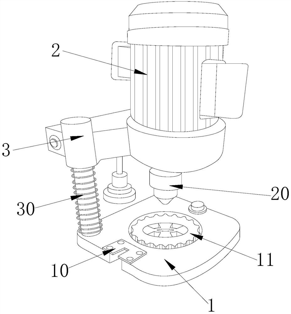
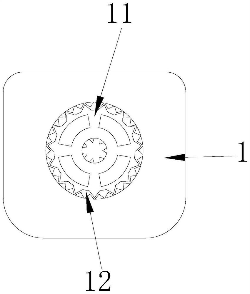
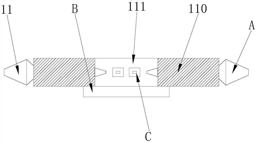
[0031] Embodiment 1: When in use, by placing the workpiece in the transmission groove 12 or in the rotation groove 111, the drill bit 20 is used to perform drilling work. When multiple drilling holes are required on the same workpiece, the pusher 120 Push the rotating plate 110 to rotate, and at the same time drive the rotating groove 111 to rotate during the rotation of the rotating plate 110, so that the workpieces on the upper surface of the rotating plate 110 can be driven to rotate, thereby pushing the workpiece to perform multi-directional drilling; The card plate E on the 120 is driven on the guide groove E1, so that the card plate E drives the card teeth D to move around the circle, and at the same time drives the card teeth D to push the rotary plate 110 to rotate; when the card teeth D push the rotary plate 110 When the push head A on the top rotates, it also drives the workpiece on the upper surface of the rotating plate 110 to rotate, thereby completing the multi-di...

Embodiment 2

[0032] Embodiment 2: When the rotating plate 110 rotates, it drives the rotating rod B to rotate at the same time, thereby driving the sawtooth C inside the rotating groove 111 to rotate, and the sawtooth C will push the workpiece inside the rotating groove 111 to perform multi-directional Drilling; at the same time, during the rotation of the rotating groove 111 and the rotating plate 110, metal debris will be pushed into the bushing plate 121, and then the debris will be introduced into the bottom of the bushing plate 121 through the holes on the bushing plate 121, and then pass through the bushing plate 121 The slag suction pipe 122 below cleans up the residue to prevent the residue from accumulating in the transmission groove 12 .

[0033] The technical progress that the present invention obtains relative to the prior art is:

[0034]1. The clamping plate on the pusher moves in a circle on the guide groove, thereby pushing the pusher on the turntable to rotate, and the pus...


PUM


Abstract

The invention discloses a chip-removing metal pipe drilling equipment. Its structure includes a base, a motor and a connecting table. The base is provided with a gusset plate, a processing turning plate and a transmission groove. The beneficial effects of the invention are: The plate moves in a circle on the guide groove, thereby pushing the pusher on the turntable to rotate, and the pusher drives the turntable to rotate during the rotation, so that a single workpiece on the upper surface of the turntable can be drilled in multiple directions. , there is no need to manually adjust the workpiece; the rotating plate drives the sawtooth inside the rotating groove to rotate during the rotation, so as to push the workpiece inside the rotating groove to rotate, and perform multi-directional drilling processing on the workpiece inside the rotating groove. At the same time, during the rotation of the rotating plate and the rotating groove, the residue is dredged into the bottom of the leakage plate, and the residue is cleaned up through the slag suction pipe, so as to prevent the metal residue from accumulating in the transmission groove and affecting the drilling work.

Description

technical field [0001] The invention relates to the field of automatic special machines, in particular to a chip-removing metal pipe drilling equipment. Background technique [0002] When the chip-removing metal tube drilling equipment involved in the automatic special machine is working, in order to ensure the quality of the drilling, it is necessary to clean the residue during the drilling process. This cleaning method is generally done by stopping the drilling equipment. Clean up after work to ensure cleanliness. [0003] Aiming at the current chip-removing metal pipe drilling equipment, a relative plan has been formulated for the following problems: [0004] The current chip-removing metal pipe drilling equipment is cleaned after stopping work. Although this method of residue cleaning is efficient, it takes a long time. At the same time, the processing base of this chip-removing metal pipe drilling It is not possible to control the position and angle of the workpiece, ...

Claims


Application Information

Patent Timeline
Patent Type & Authority Patents(China)
IPC IPC(8): B23B39/00B23Q7/00B23Q11/00
CPCB23B39/00B23Q7/00B23Q11/0046B23Q11/0067
Inventor 孙玉荣
Owner 苏州绿萃筑信息科技有限公司
Learn More