
Split type multifunctional deep hole drilling machine

A deep hole drilling machine, multi-functional technology, applied in the direction of boring/drilling, drilling/drilling equipment, parts of boring machine/drilling machine, etc., can solve the problem of high temperature of the drill bit, save time, improve accuracy and efficiency , the effect of easy operation

Pending Publication Date: 2021-01-26
李长国
View PDF1 Cites 0 Cited by
  • Summary
  • Abstract
  • Description
  • Claims
  • Application Information

AI Technical Summary

Problems solved by technology

[0006] The technical problem to be solved by the present invention is to provide a split-type multifunctional deep hole drilling machine, one of which aims to solve the problem of excessive temperature of the drill bit in order to have a cooling function; In order to achieve the effect of effectively clamping and fixing the appliance, another purpose is to have the advantage of simple structure of the clamping device and facilitate the installation and disassembly of the clamping device and the drilling machine

Method used


Image

  • Split type multifunctional deep hole drilling machine
  • Split type multifunctional deep hole drilling machine
  • Split type multifunctional deep hole drilling machine

Examples


Embodiment 1

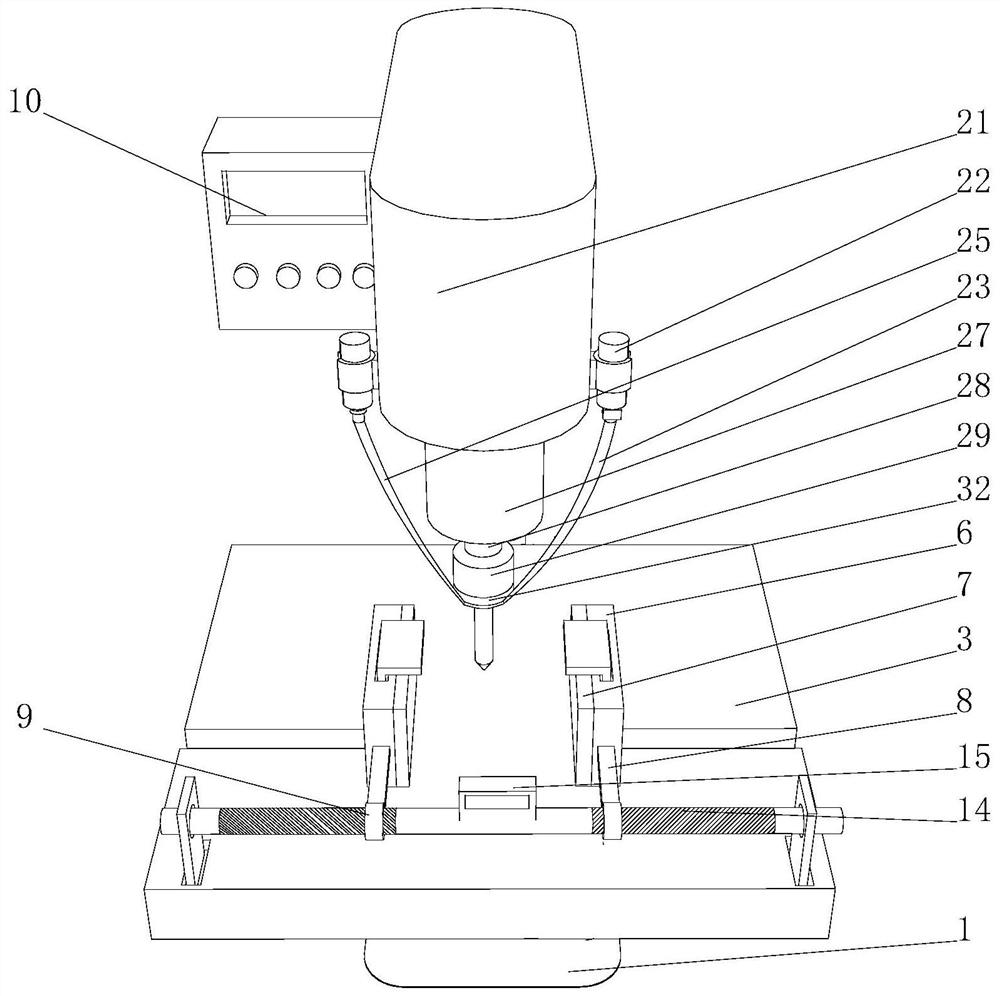
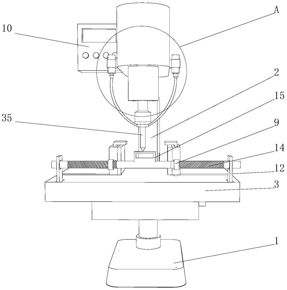
[0031] Such as Figure 1-Figure 7 As shown, the present invention provides a split-type multifunctional deep hole drilling machine, comprising a base 1, a pillar 2, a workbench 3 and a clamping device 6, the top of the base 1 is fixedly connected with a pillar 2, and the front of the pillar 2 is fixedly connected with a The workbench 3 is provided with a chute 4 at the left and right ends of the top of the workbench 3, the inner wall of the chute 4 is slidably connected with a sliding block 5, and the top of the sliding block 5 is fixedly connected with a clamping device 6, and the clamping device 6 The fronts of the connecting rods 8 are fixedly connected with connecting rods 8, and the opposite surfaces of the clamping device 6 are provided with damping sponges 7, the fronts of the connecting rods 8 are fixedly connected with threaded sleeves 9, and the inner walls of the threaded sleeves 9 are all threaded with two-way bolts 14 , the base 1 is used to fix and support the sp...

Embodiment 2

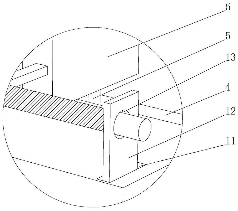
[0033] Such as Figure 1-5 As shown, on the basis of Embodiment 1, the present invention provides a technical solution: the top left and right sides of the workbench 3 are provided with fixing grooves 11, the inner wall of the fixing groove 11 is movably connected with a fixing plate 12, and the fixing plate 12 The side is provided with a circular groove 13, and the fixed plate 12 is respectively movably connected with the left and right ends of the two-way bolt 14 through the circular groove 13 provided. Movable slot 16, the bottom of the inner wall of the movable slot 16 is provided with a fixed rod 17, the top of the fixed rod 17 is provided with a lift chamber 18, the inwall of the lift chamber 18 is movably connected with a push-pull rod 19, and the top of the push-pull rod 19 is fixedly connected with a top fixed block 20. Install the threaded sleeve 9 on the two-way bolt 14, insert both ends of the two-way bolt into the circular groove 13, then insert the fixing plate 1...

Embodiment 3

[0035] Such as Figure 1-7As shown, on the basis of Embodiment 1 and Embodiment 2, the present invention provides a technical solution: the top of the pillar 2 is fixedly connected with a working box 21, and the left side of the working box 21 is provided with a numerical control device 10, and the numerical control device 10 The function is to adjust and control the split multi-functional deep hole drilling machine. The right side of the working box 21 is movably connected with a cooling liquid storage bottle 22 through a fixed device provided. Cooling liquid, the bottom of the cooling liquid storage bottle 22 is provided with a liquid inlet pipe 23, and the top of the liquid inlet pipe 23 is provided with an electric control valve 24, which controls the numerical control device 10 to control the closing and opening of the electric control valve 24, the working box The bottom of 21 is fixedly connected with a cylinder 27, and the output end of the cylinder 27 is movably conne...


PUM


Abstract

The invention discloses a split type multifunctional deep hole drilling machine, and relates to the technical field of deep hole drilling machines. The split type multifunctional deep hole drilling machine comprises a base, a supporting column, a workbench and clamping devices. The top of the base is fixedly connected with the supporting column, and the front face of the supporting column is fixedly connected with the workbench. Sliding grooves are formed in the left end and the right end of the top of the workbench respectively. Sliding blocks are slidably connected to the inner walls of thesliding grooves, the clamping devices are fixedly connected to the tops of the sliding blocks, and connecting rods are fixedly connected to the front faces of the clamping devices. According to the split type multifunctional deep hole drilling machine, a high-temperature drill bit obtained after machining is completed can be conveniently cooled, rapid cooling of the drill bit is facilitated, timeis saved for workers to replace the drill bit, meanwhile, a machined tool can be effectively clamped, the drilling precision and efficiency of the split type multifunctional deep hole drilling machineare improved, and due to the fact that the clamping devices are convenient to operate and simple in structure, the clamping devices can be conveniently installed to and detached from the workbench.

Description

technical field [0001] The invention relates to a split-type multifunctional deep hole drilling machine and relates to the technical field of deep hole drilling machines. Background technique [0002] Deep hole drilling machine, which is different from the traditional hole processing method, mainly relies on specific drilling technology (such as gun drilling, BTA drilling, ejector drilling, etc.) Special machine tools for drilling are collectively referred to as deep hole drilling machines. It represents advanced and efficient hole processing technology. The processing has high precision, high efficiency and high consistency. Accurate position, good dimensional accuracy; high straightness and coaxiality, high surface finish and repeatability. It can easily process various forms of deep holes, and can also solve various special forms of deep holes, such as cross holes, oblique holes, blind holes and flat bottom blind holes. It can not only be used to process deep holes wit...

Claims


Application Information

Patent Timeline
Patent Type & Authority Applications(China)
IPC IPC(8): B23B41/02B23B47/00B23Q3/06B23Q11/10
CPCB23B41/02B23B47/00B23Q3/06B23Q11/10
Inventor 李长国
Owner 李长国
Learn More