It can be installed on the universal shearing machine for the positioning of the shearing angle of rectangular plates.

A shearing machine and angle positioning technology, which is applied in the direction of shearing devices, metal processing equipment, shearing machine accessories, etc., can solve the problems that the line drawing method cannot meet the requirements, the error size is large, and the size requirements are high, so as to avoid pulling Poor extension, increased shear angular velocity, and strong flexibility

Active Publication Date: 2021-04-16
NINGBO FOTILE KITCHEN WARE CO LTD
View PDF7 Cites 0 Cited by
  • Summary
  • Abstract
  • Description
  • Claims
  • Application Information

AI Technical Summary

Problems solved by technology

[0003] In the actual operation process of the traditional line drawing method, the edge of the plate is limited by factors such as workers, the size of the plate, and the light on site, and the error size is relatively large; each operation must be aligned with the edge of the plate with the naked eye , the operating efficiency is also low
Compared with traditional sink stretching, dishwasher sink stretching not only has a deeper stretching depth, but also has much higher dimensional requirements. Therefore, the precision of the cutting angle of the plate is also higher, and the traditional line drawing method cannot meet the requirements at all.

Method used


Image

  • It can be installed on the universal shearing machine for the positioning of the shearing angle of rectangular plates.
  • It can be installed on the universal shearing machine for the positioning of the shearing angle of rectangular plates.
  • It can be installed on the universal shearing machine for the positioning of the shearing angle of rectangular plates.

Examples


Embodiment Construction

[0018] The present invention will be further described in detail below in conjunction with the accompanying drawings and embodiments.

[0019] Such as Figure 1~5 Shown is a preferred embodiment of the present invention.

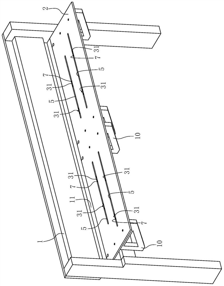
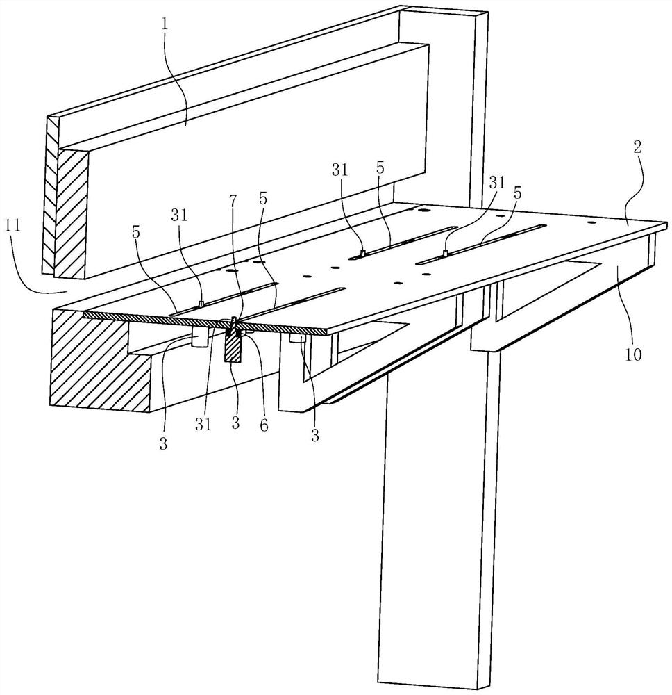
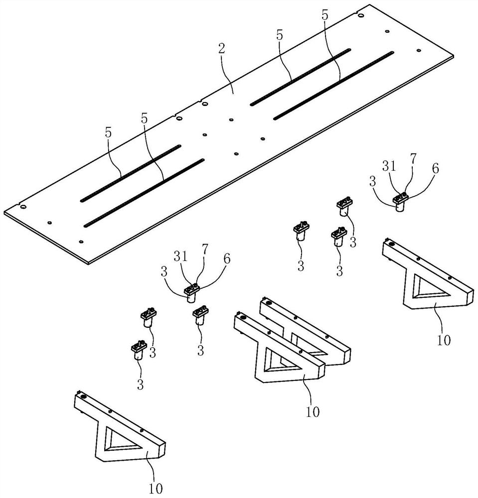
[0020] A pallet mechanism that can be installed on a general-purpose shearing machine for positioning the shearing angle of a rectangular plate includes a platen 2 fixed on a shearing machine 1 for placing a rectangular plate 4 . The front end of the shearing machine 1 is fixed with a plurality of support frames 10, and the platen 2 rests on the support frames 10 and is fixed on the support frames 10 by screws.

[0021] Two sets of positioning structures for positioning the edges of the rectangular plates 4 are fixed on the platen 2 in this embodiment. One side 41 of the rectangular plate 4 is used to limit the position, and the rods 31 of the other pair of electric telescopic rods 3 are used to limit the other side 41 adjacent to the rectangular plate 4. ...


PUM


Abstract

The invention relates to a supporting plate mechanism that can be installed on a general-purpose shearing machine for positioning the cutting angle of a rectangular plate, including a platen fixed on the platen shearing machine; it is characterized in that at least two sets of positioning structures are fixed on the platen , each group of positioning structures includes two pairs of electric telescopic rods, wherein the rods of one pair of electric telescopic rods limit one side of the rectangular plate, and the rods of the other pair of electric telescopic rods limit the other side of the adjacent rectangular plate. The side is limited, and each pair of electric telescopic rods includes two electric telescopic rods fixed at the bottom of the table. The rods of each electric telescopic rod can extend upwards or retract downwards and hide on the top surface of the table. below. The positioning dimension of this mechanism is stable and accurate. At the same time, the shearing angular speed is greatly increased, and it is not affected by the light on site, and there is no need to visually observe whether the position of the drawn line is aligned with the edge of the plate, which realizes foolish operation and greatly improves the working efficiency of the shearing plate.

Description

technical field [0001] The invention relates to an auxiliary device of a shearing machine, in particular to a supporting plate mechanism which can be installed on a general-purpose shearing machine for positioning the shearing angle of a rectangular plate. Background technique [0002] The sink is formed by stretching the sheet. In order to prevent stress cracking during the stretching process in the sink industry, it is generally necessary to cut the corners of the right angles of the rectangular sheet multiple times, which can be cut twice. Generally, the corners are cut at most three times, and then stretched to eliminate the stress concentration at the corners of the rectangular sheet and prevent cracking and whitening during the stretching process. The traditional old method is the line drawing method. [0003] In the actual operation process of the traditional line drawing method, the edge of the plate is limited by factors such as workers, the size of the plate, and t...

Claims


Application Information

Patent Timeline
Patent Type & Authority Patents(China)
IPC IPC(8): B23D33/02
CPCB23D33/02
Inventor 陈时先王镜淇
Owner NINGBO FOTILE KITCHEN WARE CO LTD
Why Eureka
Try Eureka