Kaplan turbine blade operating mechanism

An operating mechanism and water turbine technology, applied in the direction of machines/engines, mechanical equipment, hydroelectric power generation, etc., can solve the problems of poor casting process, large quantity, and difficult design of parts and runners, and achieve shortened design and manufacturing cycle, low cost, The effect of simple structure

Pending Publication Date: 2020-05-29
CHONGQING WATER TURBINE WORKS
View PDF0 Cites 0 Cited by
  • Summary
  • Abstract
  • Description
  • Claims
  • Application Information

AI Technical Summary

Problems solved by technology

In addition to introducing the slider drive mode, the other two operating mechanisms need to use a connecting rod to transition. There are two sets of friction pairs and related parts at both ends of the connecting rod, which occupy a large space and a l

Method used


Image

  • Kaplan turbine blade operating mechanism
  • Kaplan turbine blade operating mechanism
  • Kaplan turbine blade operating mechanism

Examples


Embodiment 1

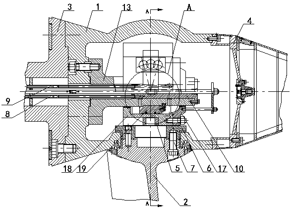
[0019] Embodiment 1: as figure 1 , 2 As shown in . and 3, a paddle turbine blade operating mechanism includes a runner body 1, at least three blades 2 are arranged on the runner body 1, and water turbines are respectively arranged at both ends of the runner body 1. The main shaft 3 and the drain cone 4 are provided in the runner body 1 with an operating oil pipe whose end passes through the main shaft 3 of the water turbine and penetrates into the runner body 1, and an oil inlet and outlet mechanism is arranged on the penetrating end of the operating oil pipe. A super relay mechanism communicating with the oil inlet and outlet mechanism is arranged on the oil inlet and outlet mechanism, and the super relay mechanism is connected with the blade 2 through the slider 5 and the rocker arm 6 .

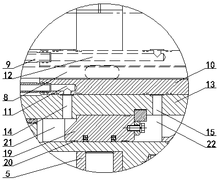
[0020] Wherein, the operating oil pipe includes the operating oil pipe A8 and the operating oil pipe B9; the oil inlet and outlet mechanism includes the oil receiving shaft 10, and the oil...

Embodiment 2

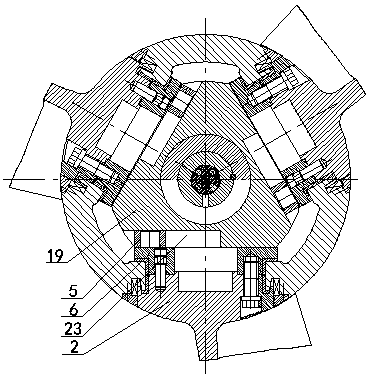
[0026] Embodiment 2: as Figure 4 As shown, the section of the super servomotor cylinder 18 is square, and four chutes 23 are evenly arranged on the super servomotor cylinder 18; Inside the chute 23 ; there are four blades 2 , and each slider 5 is connected to the corresponding blade 2 through a rocker arm 6 .

Embodiment 3

[0027] Embodiment 3: as Figure 5 As shown, the section of the super servomotor cylinder 18 is pentagonal, and five chutes 23 are evenly arranged on the super servomotor cylinder 18; There are five slide slots 23; there are five blades 2, and each slider 5 is connected to the corresponding blade 2 through a rocker arm 6, respectively.

[0028] Of course, according to actual needs, the super servomotor cylinder 18 can also be made into a hexagonal or octagonal shape, and the corresponding blades 2 can also adopt six blades or eight blades.


PUM


Abstract

The invention discloses a Kaplan turbine blade operating mechanism. The blade operating mechanism comprises a runner body (1), wherein at least three blades (2) are arranged on the runner body (1), awater turbine main shaft (3) and a runner cone (4) are arranged at the two ends of the runner body (1) correspondingly, an operating oil pipe is arranged in the runner body (1), one end of the operating oil pipe penetrates through the water turbine main shaft (3) and penetrates into the runner body (1), an oil inlet and outlet mechanism is arranged at the penetrating-in end of the operating oil pipe, a super relay mechanism communicating with the oil inlet and outlet mechanism is arranged on the oil inlet and outlet mechanism, and the super relay mechanism is connected with a blade (2) throughsliding blocks (5) and rocker arms (6). The blade operating mechanism has the advantages of being simple in structure, ingenious in design, reliable in use and low in cost, the number of parts can bereduced, the space is saved, the manufacturing difficulty is lowered, the design and manufacturing period is shortened, and the cost is saved.

Description

technical field [0001] The invention relates to a paddle water turbine, in particular to a blade operating mechanism of a paddle water turbine. Background technique [0002] At present, in rotary paddle turbines, the operating mechanism of the blades of the turbine is assembled in the runner body of the rotating part, and it must be completed in a given limited space. Therefore, it is very important to arrange the operating mechanism in the limited space to save space. There are typically two types of existing blade operating mechanisms: one is a double-acting fixed servomotor, the piston is matched with the operating frame, and the operating frame drives the blade through a connecting rod; the other is a double-acting piston cylinder with an operating frame, and the piston is fixed. , also drives the paddle through the connecting rod. In addition to introducing the slider drive mode, the other two operating mechanisms need to use a connecting rod to transition. There are t...

Claims


Application Information

Patent Timeline
IPC IPC(8): F03B15/00F03B3/14
CPCF03B3/145F03B15/00F05B2270/328F05B2270/506Y02E10/20Y02P70/50
Inventor 王怀平程烈蓉
Owner CHONGQING WATER TURBINE WORKS
Why Eureka
Try Eureka