Long-distance material energy conveying pipeline joint air tightness detection system

A technology for air tightness detection and pipeline transportation, which is applied in fluid tightness testing, liquid tightness measurement using liquid/vacuum degree, and detecting the appearance of fluid at leakage points, etc., which can solve the problem of high cost and inconvenient plugging. Tightness, can not guarantee the tightness and other problems, to ensure the effect of ensuring accuracy and increasing friction

Inactive Publication Date: 2020-05-29
倪立兵
View PDF0 Cites 10 Cited by
  • Summary
  • Abstract
  • Description
  • Claims
  • Application Information

AI Technical Summary

Problems solved by technology

[0003] However, the following problems exist in the air-tightness detection operation of the existing energy pipeline laying joints, a. It is necessary to manually use tools to seal and block the inside of the pipeline. Manual blocking cannot guarantee the sealing performance, and there are cases where the sealing is not tight, which affects the pipeline. The accuracy of air tightness detection, manual and simple blockage, the friction between the blockage and the pipe is small, and when the inflation pressure is too high, it is easy to cause the blockage to move under the action of air pressure b. For pipe fittings of different diameters, it is necessary to prepare Corresponding blocking objects are costly and affect the efficiency of pipeline construction and laying
[0004] For the technical problems existing in the airtightness detection of the current energy pipeline laying, personnel in the related technical field have conducted research and made adaptation improvements, such as the Chinese utility model patent No. 2014200671177, a pressure pipeline airtightness detection device, which can improve the efficiency of air tightness detection, but it does not mention the problems mentioned above

Method used


Image

  • Long-distance material energy conveying pipeline joint air tightness detection system
  • Long-distance material energy conveying pipeline joint air tightness detection system
  • Long-distance material energy conveying pipeline joint air tightness detection system

Examples


Embodiment Construction

[0032] The embodiments of the present invention will be described in detail below with reference to the accompanying drawings, but the present invention can be implemented in many different ways defined and covered by the claims.

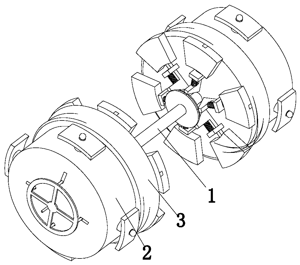
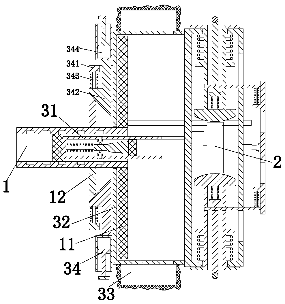
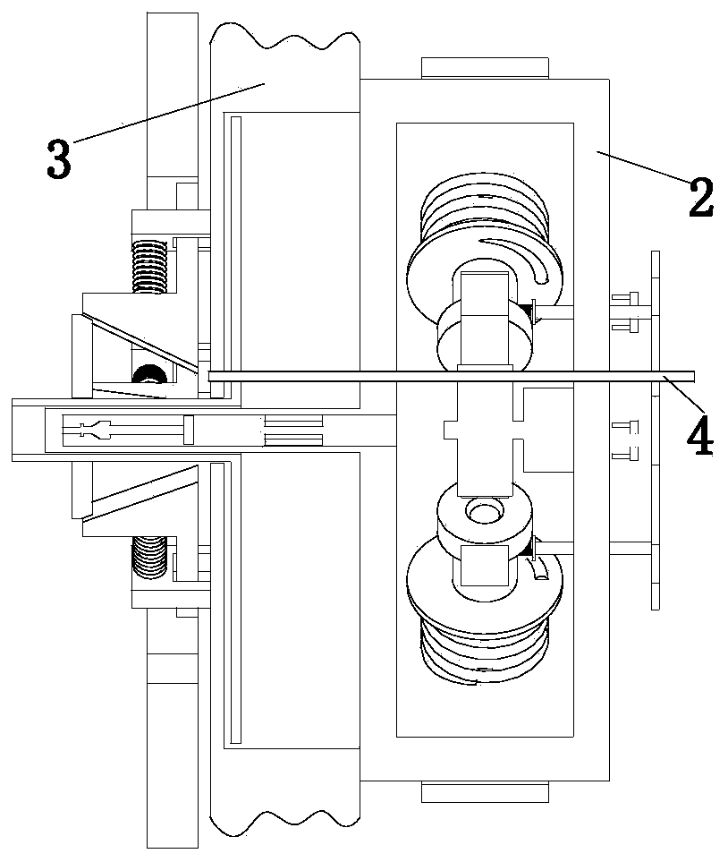
[0033] Such as Figure 1 to Figure 11 As shown in the figure, an airtightness detection system at the joint of a long-distance material and energy transmission pipeline includes a connecting pipe 1, and the front and rear ends of the connecting pipe 1 are symmetrically provided with a sealing device 3, and the side wall of the sealing device 3 is equipped with a positioning locking device. device 2.

[0034] The positioning and locking device 2 includes a circular frame 21, the side wall of the circular frame 21 is uniformly provided with a telescopic hole along its circumferential direction, an auxiliary locking mechanism 22 is arranged in the telescopic hole, and a card is installed on the outer wall of the circular frame 21. Tighten the cylinder...


PUM


Abstract

The invention relates to a long-distance material energy conveying pipeline joint air tightness detection system, which comprises a connecting pipe. Sealing devices are symmetrically arranged at the front end and the rear end of the connecting pipe, and positioning locking devices are arranged on the side walls of the sealing devices. According to the invention, the following problems in the air tightness detection operation of the existing energy pipeline laying joint can be solved: a, the interior of a pipeline needs to be manually sealed and blocked by using tools, the leakproofness cannotbe ensured by manual blockage, the condition of untight plugging exists, the pipeline airtightness detection accuracy is influenced, blockage is manually and simply carried out, the friction force between a blockage object and a pipeline is small, when the inflation pressure is too large, the blockage object is likely to move under the action of air pressure; b, corresponding blockage objects needto be prepared for pipe fittings with different diameters, the cost is high, and the pipeline construction and laying efficiency is influenced.

Description

technical field [0001] The invention relates to the technical field of energy transmission, in particular to an air-tightness detection system for the joints of long-distance material and energy transmission pipelines. Background technique [0002] Energy transportation refers to the transportation of coal, oil, natural gas and electricity in the circulation field. Pipeline transportation is the main mode of transportation of crude oil and natural gas. The transportation of crude oil and natural gas has strict requirements on the sealing of pipelines. For air tightness testing, especially the detection of pipeline connections, the airtightness of pipeline connections must be accurately checked to ensure the safety of energy transmission. [0003] However, the following problems exist in the air-tightness detection operation of the existing energy pipeline laying joints, a. It is necessary to manually use tools to seal and block the inside of the pipeline. Manual blocking can...

Claims


Application Information

Patent Timeline
Patent Type & Authority Applications(China)
IPC IPC(8): G01M3/04F16J15/10
CPCF16J15/104G01M3/022G01M3/04
Inventor 倪立兵姚孝明张纪彬
Owner 倪立兵
Why Eureka
Try Eureka