Sampling mechanism for high-temperature waste gas laboratory detection

A high-temperature waste gas, laboratory technology, used in sampling, sampling devices, measuring devices, etc., can solve the problems of clogging of sampling tools, air bag sampling, condensation of volatile pollutants, etc., to achieve the effect of simple structure and improved authenticity

Inactive Publication Date: 2020-05-29
张小娟
View PDF0 Cites 0 Cited by
  • Summary
  • Abstract
  • Description
  • Claims
  • Application Information

AI Technical Summary

Problems solved by technology

[0002] Existing portable gas sampling and analysis instruments can only analyze one or several specific harmful gas concentrations in real time while sampling. However, there may be a wide variety of pollutants in high-temperature exhaust gases, and portable analyzers cannot comprehensively detect high-temperature For all pollutant components of the exhaust gas, a special gas analysis laboratory is required to comprehensively analyze the concentration of all pollutants in the sampled gas; therefore, it is necessary to sample and store real high-temperature flue gas samples on site, and then bring the samples to a special A gas analysis laboratory for systematic gas analysis;
[0003] However, due to the high temperature of the discharge port of the high-temperature flue gas, air bag sampling cannot be used directly, and the authenticity of the samples taken outside the discharge port is not high, so it is necessary to use a longer sampling tool to extend into the interior of the high-temperature discharge port , and then suck out the real exhaust gas, and the high-temperature flue gas is prone to condensation during the process of flowing into the long sampling tool, and some volatile pollutants will also condense, resulting in the final collected gas sample. The degree of reduction is not high, and the condensed water and other pollutants will remain in the sampling tool, which will also cause blockage of the sampling tool over time

Method used


Image

  • Sampling mechanism for high-temperature waste gas laboratory detection
  • Sampling mechanism for high-temperature waste gas laboratory detection
  • Sampling mechanism for high-temperature waste gas laboratory detection

Examples


Embodiment Construction

[0040] The present invention will be further described below in conjunction with the accompanying drawings.

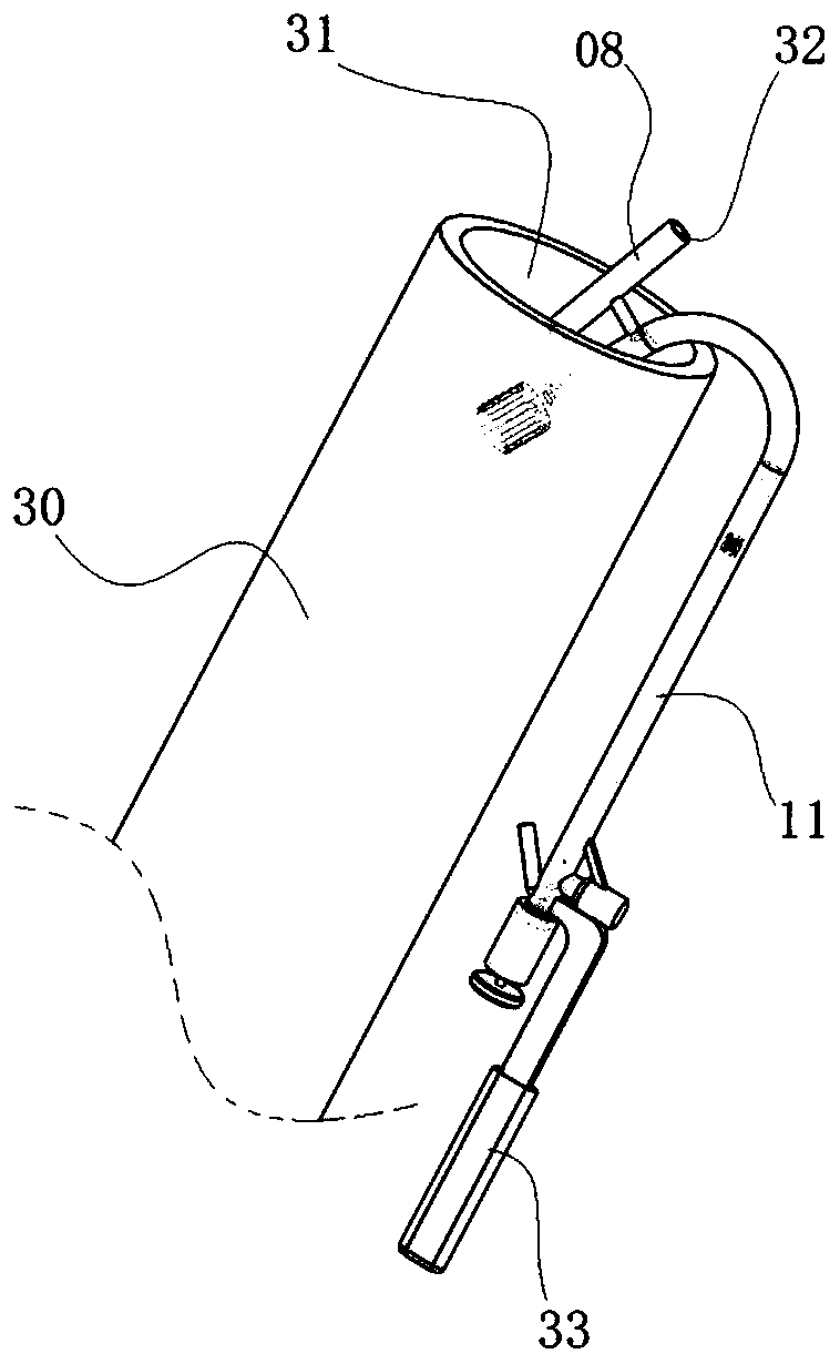
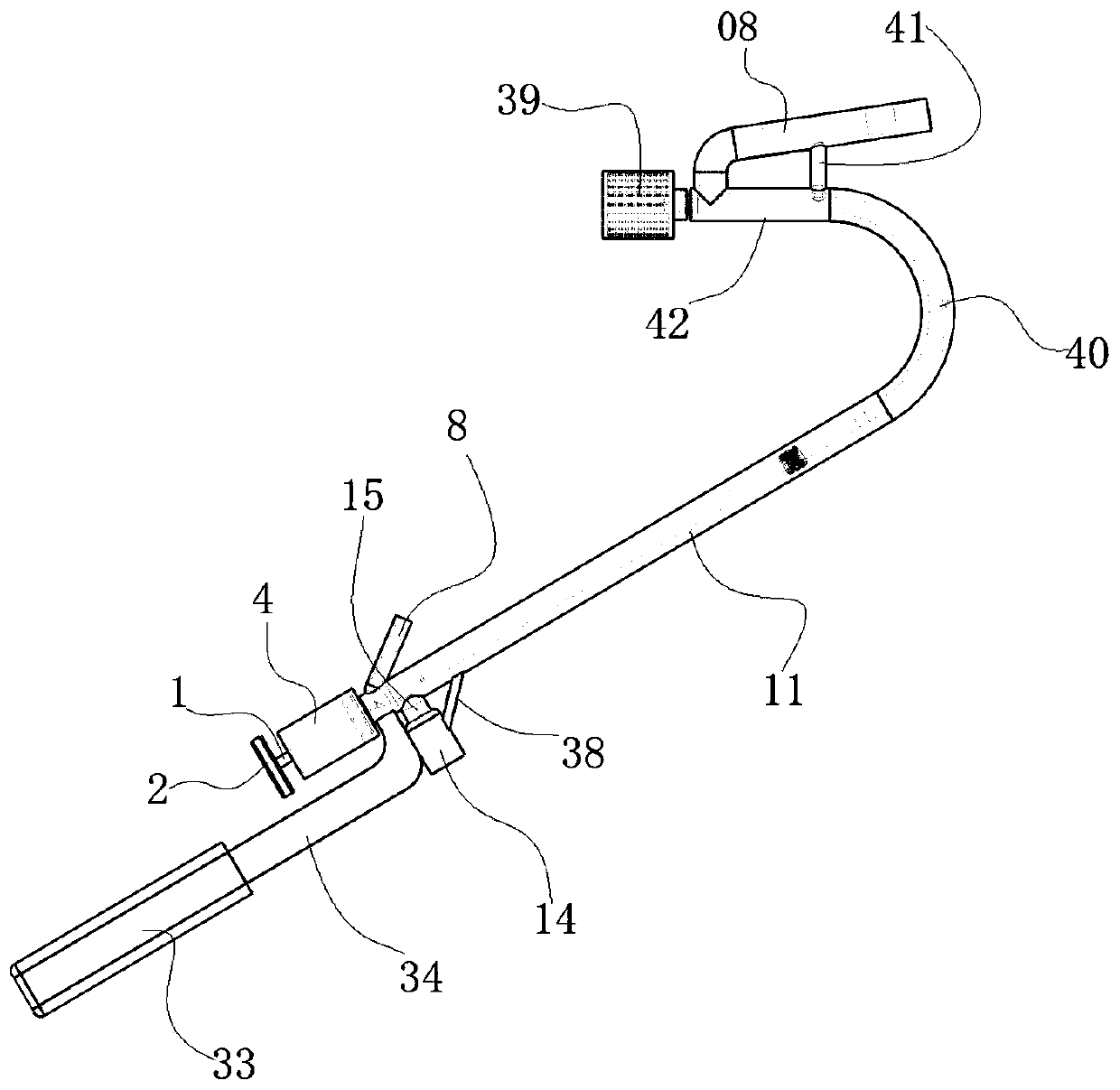
[0041] as attached Figures 1 to 14 The sampling mechanism shown in the high-temperature exhaust gas laboratory test includes a high-temperature exhaust pipe 30, and one end of the high-temperature exhaust pipe 30 is a high-temperature exhaust gas exhaust port 31;

[0042] It also includes a long rod-shaped sampling tool. One end of the sampling tool is set in a curved structure. Part of the smoke sample.

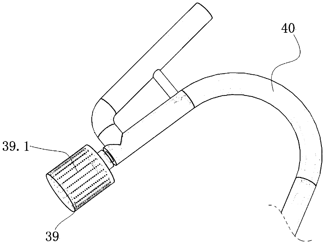
[0043]The sampling tool includes a hard outer tube body structure, and the outer tube body structure includes a first straight outer tube 11, an arc-shaped curved outer tube 40, and a second straight outer tube 42 that are sequentially integrated and communicated along the length direction. The end of the outer tube 11 is detachably connected to the sample storage tube 4, and the end of the second linear outer tube 42 is a sampling end, and the sampling end is als...


PUM


Abstract

The invention discloses a sampling mechanism for high-temperature waste gas laboratory detection. The mechanism comprises a high-temperature exhaust pipe, wherein one end of the high-temperature exhaust pipe is a high-temperature waste gas exhaust port, the device further comprises a long-rod-shaped sampling tool, one end of the sampling tool is arranged to be of a bent structure, a tail end of the bent structure is a sampling end, and the sampling end can extend into the high-temperature waste gas exhaust port and can suck away a part of flue gas samples flowing in the high-temperature exhaust pipe. The mechanism is advantaged in that the mechanism is simple in structure, the hot gas is adopted to heat a wall of the heat exchange pipe, so the gas in a sample storage barrel is completely consistent with gas flowing in the high-temperature exhaust pipe in a condensation preventing mode, and authenticity of gas analysis is improved.

Description

technical field [0001] The invention belongs to the field of laboratory gas sampling. Background technique [0002] Existing portable gas sampling and analysis instruments can only analyze one or several specific harmful gas concentrations in real time while sampling. However, there may be a wide variety of pollutants in high-temperature exhaust gases, and portable analyzers cannot comprehensively detect high-temperature For all pollutant components of the exhaust gas, a special gas analysis laboratory is required to comprehensively analyze the concentration of all pollutants in the sampled gas; therefore, it is necessary to sample and store real high-temperature flue gas samples on site, and then bring the samples to a special A gas analysis laboratory for systematic gas analysis; [0003] However, due to the high temperature of the discharge port of the high-temperature flue gas, air bag sampling cannot be used directly, and the authenticity of the samples taken outside t...

Claims


Application Information

Patent Timeline
IPC IPC(8): G01N1/22
CPCG01N1/2202G01N1/2205G01N1/2258G01N2001/2261
Inventor 张小娟
Owner 张小娟
Why Eureka
Try Eureka