
Method and system for carrying out field calibration on transient characteristics of direct-current voltage measuring device

A measuring device, a technology of DC voltage, applied in the direction of measuring device, measuring electrical variables, instruments, etc., can solve the problems of on-site verification of transient characteristics of DC voltage measuring device, etc.

Inactive Publication Date: 2020-05-29
CHINA ELECTRIC POWER RES INST +2
View PDF8 Cites 3 Cited by
  • Summary
  • Abstract
  • Description
  • Claims
  • Application Information

AI Technical Summary

Problems solved by technology

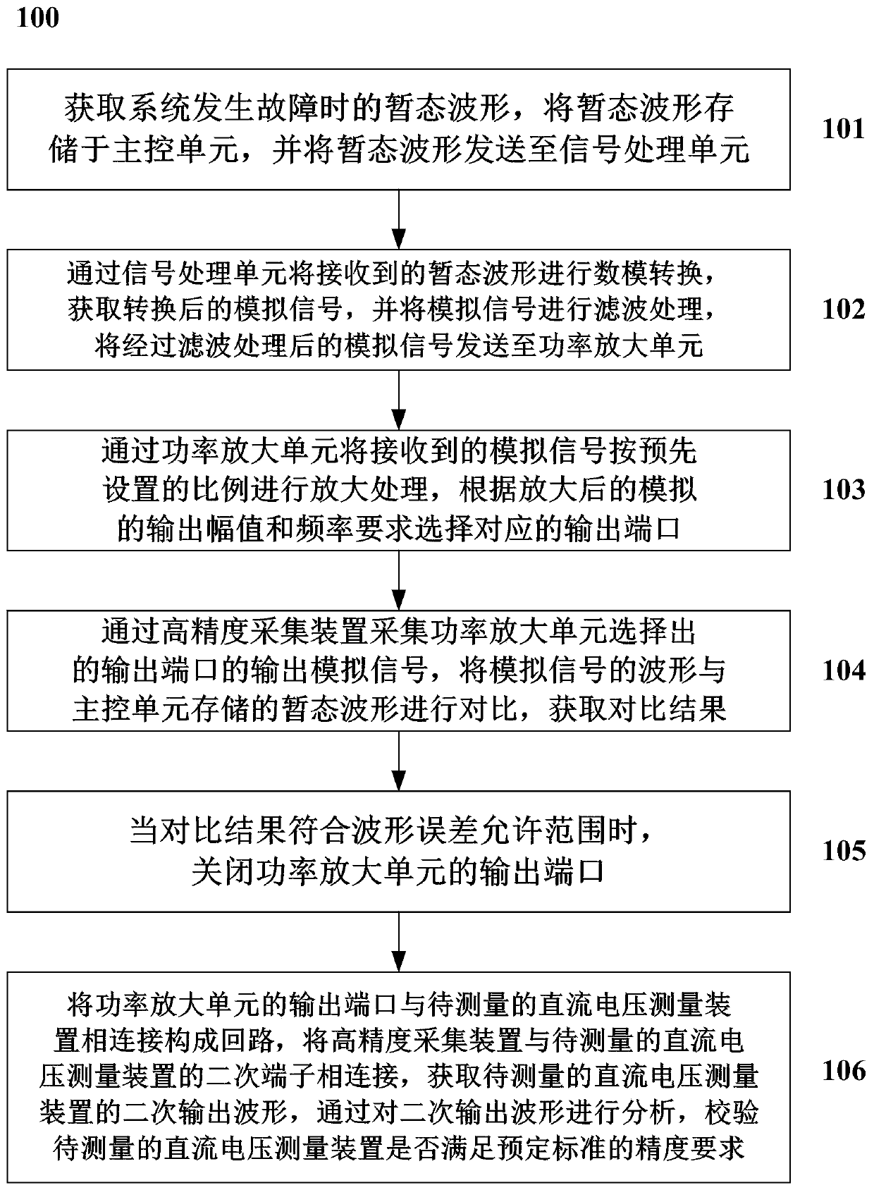
[0005] The technical solution of the present invention provides a method and system for on-site verification of the transient characteristics of a DC voltage measuring device to solve the problem of how to perform on-site verification of the transient characteristics of a DC voltage measuring device

Method used


Image

  • Method and system for carrying out field calibration on transient characteristics of direct-current voltage measuring device
  • Method and system for carrying out field calibration on transient characteristics of direct-current voltage measuring device
  • Method and system for carrying out field calibration on transient characteristics of direct-current voltage measuring device

Examples


Embodiment Construction

[0033] Exemplary embodiments of the present invention will now be described with reference to the drawings; however, the present invention may be embodied in many different forms and are not limited to the embodiments described herein, which are provided for the purpose of exhaustively and completely disclosing the present invention. invention and fully convey the scope of the invention to those skilled in the art. The terms used in the exemplary embodiments shown in the drawings do not limit the present invention. In the figures, the same units / elements are given the same reference numerals.

[0034] Unless otherwise specified, the terms (including scientific and technical terms) used herein have the commonly understood meanings to those skilled in the art. In addition, it can be understood that terms defined by commonly used dictionaries should be understood to have consistent meanings in the context of their related fields, and should not be understood as idealized or over...


PUM


Abstract

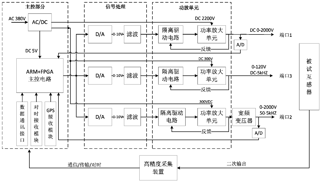
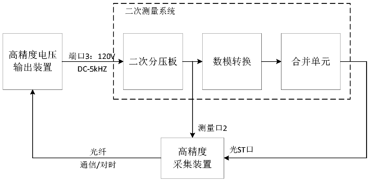
The invention discloses a method and a system for carrying out field calibration on the transient characteristics of a direct-current voltage measuring device. The method comprises the following steps: acquiring a transient waveform when a system has a fault, storing the transient waveform in a main control unit, performing digital-to-analog conversion on the transient waveform through a signal processing unit, and sending an analog signal subjected to filtering processing to a power amplification unit; amplifying the analog signal through the power amplification unit, and selecting a corresponding output port; collecting an output analog signal of the power amplification unit through a high-precision collection device, comparing the waveform of the analog signal with a transient waveformstored in the main control unit, and closing an output port of the power amplification unit when a comparison result conforms to a waveform error allowable range; and connecting an output port of thepower amplification unit to a direct-current voltage measuring device to be measured to form a loop, and connecting the high-precision acquisition device to a secondary terminal of the direct-currentvoltage measuring device to obtain a secondary output waveform of the direct-current voltage measuring device to be measured.

Description

technical field [0001] The invention relates to the technical field of electric power detection, and more specifically, relates to a method and system for on-site verification of the transient characteristics of a DC voltage measuring device. Background technique [0002] The prior art (CN108051769A) discloses a capacitive voltage transformer transient response test device and test method, including a circuit breaker, a voltage transformer, a phase selection opening and closing controller, a data acquisition photoelectric conversion module, an upper computer and a measurement and control unit. module. In the prior art, after the power supply of the verified capacitive voltage transformer is short-circuited, whether the secondary voltage of the capacitive voltage transformer can decay to a specified value relative to the peak value of the voltage before the short circuit within a specified time. The technical method adopted is to control the phase angle of the power frequenc...

Claims


Application Information

Patent Timeline
IPC IPC(8): G01R35/00G01R35/02
CPCG01R35/005G01R35/02
Inventor 邱进吴士普冯宇汪本进毛安澜徐思恩陈晓明王玲李璿杜砚余春雨
Owner CHINA ELECTRIC POWER RES INST
Learn More