
Multispectral polarization image defogging method combined with sky light polarization model

A technology of polarized image and sky light, applied in image enhancement, image analysis, image data processing and other directions, can solve the problems of affecting the dehazing results, unable to select the sky area correctly, misestimating the atmospheric light intensity and atmospheric polarization degree, etc. To achieve the effect of improving the dehazing effect

Inactive Publication Date: 2020-05-29
BEIHANG UNIV
View PDF1 Cites 10 Cited by
  • Summary
  • Abstract
  • Description
  • Claims
  • Application Information

AI Technical Summary

Problems solved by technology

The model of this method is simple and easy to implement, and can effectively restore the visibility of the scene, but there are still some problems: when there is no sky area in the image or there are some high-brightness objects or strong light sources in the image, the sky area cannot be selected correctly , and then wrongly estimate the atmospheric light intensity and atmospheric polarization degree at infinity, which will affect the final dehazing result
This method is based on the partial polarization of skylight, but in dense fog conditions, where the degree of polarization of skylight is close to zero, this method will fail

Method used


Image

  • Multispectral polarization image defogging method combined with sky light polarization model
  • Multispectral polarization image defogging method combined with sky light polarization model
  • Multispectral polarization image defogging method combined with sky light polarization model

Examples


Embodiment Construction

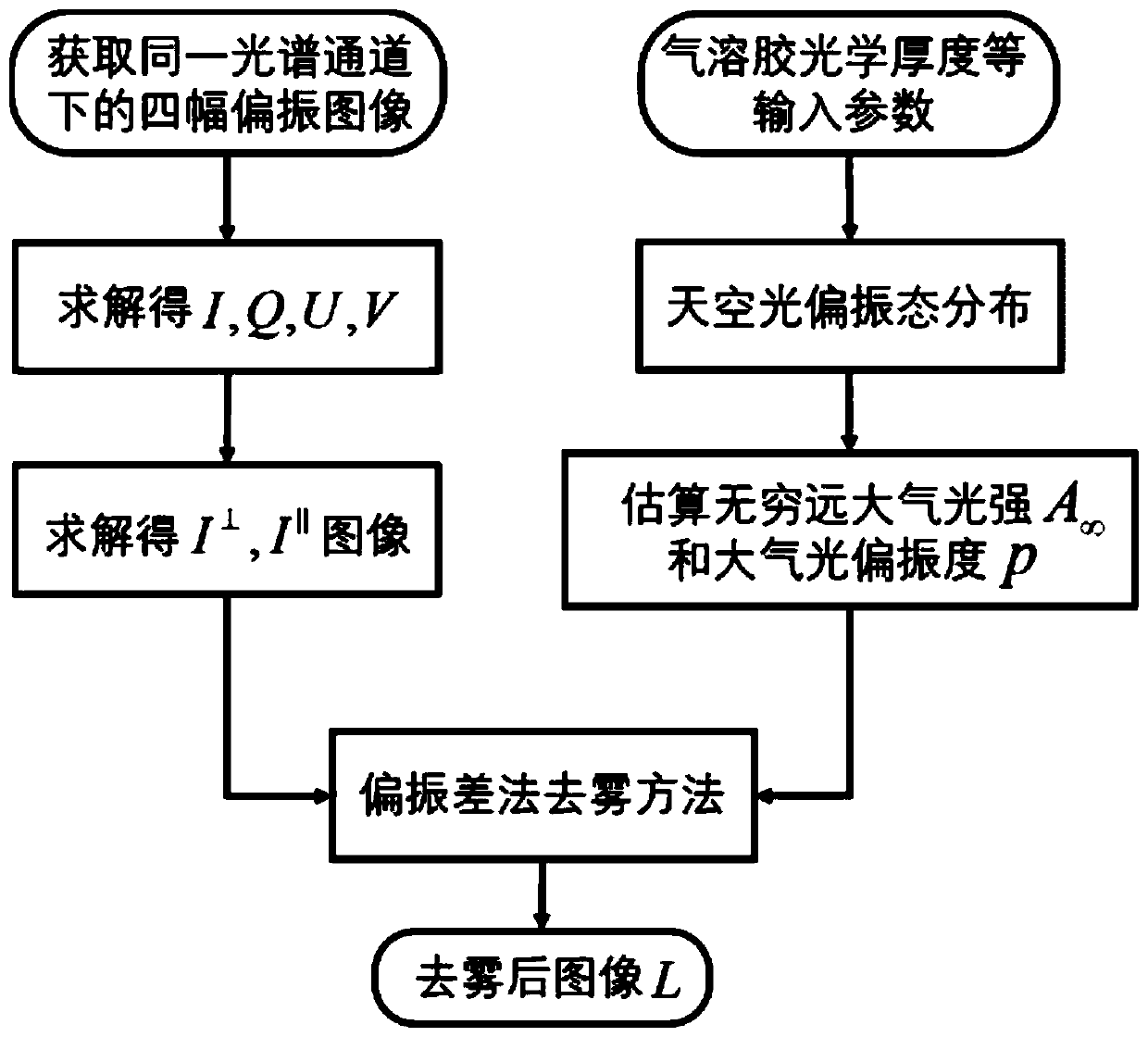
[0038] Below in conjunction with accompanying drawing and specific embodiment the present invention is described in further detail, figure 1 It is a flow chart of the method of the present invention.

[0039] The present invention proposes a multi-spectral polarization image defogging method combined with the sky light polarization model, which is realized by the following steps:

[0040](1) Using a multi-spectral polarization imaging detection system based on a liquid crystal phase variable retarder to image the scene, and obtain four polarization images under different spectral channels, as shown in Figure 2. By calculating the Stokes vector (I, Q, U, V), using the relationship between the Stokes vector and the Muller matrix, the two images (I ⊥ ,I || ). The linear polarizer model is as follows:

[0041]

[0042] where (I in ,Q in ,U in ,V in ) is the incident polarized light Stokes vector, (I out ,Q out ,U out ,V out ) is the Stokes vector of outgoing polariz...


PUM


Abstract

The invention provides a multispectral polarization image defogging method combined with a sky light polarization model, which comprises the following steps: under a foggy weather condition, firstly,acquiring polarization images under different spectrum channels by using a multispectral polarization imaging detection system, and simultaneously measuring the aerosol optical thickness of a corresponding spectrum band by using a sun photometer; secondly, inputting a detection waveband, a solar zenith angle, aerosol optical thickness, aerosol particle scattering information and the like into a sky light polarization model; obtaining a sky light polarization state distribution diagram through simulation, selecting a sky area in a horizontal field angle on a detection azimuth angle, and obtaining the average value of the light intensity and the average value of the polarization degree to serve as an atmospheric light intensity value and an atmospheric light polarization degree value at infinity respectively. And finally, defogging the polarization images of different spectrum channels by using a defogging method based on polarization difference. According to the method, the problem thatthe polarization degree atmospheric light information is estimated mistakenly when no sky area exists in a multispectral polarization image scene or some high-brightness objects exist in the scene issolved.

Description

technical field [0001] The invention belongs to the field of near-surface remote sensing image processing, and relates to a multi-spectral polarization image defogging method combined with a sky light polarization model, which is used to improve the image quality of optical detection system imaging under foggy weather and other harsh environmental conditions. Background technique [0002] In foggy weather conditions, due to the scattering phenomenon of atmospheric aerosol particles, the quality of images obtained by outdoor imaging systems is seriously degraded. Therefore, how to effectively remove the influence of fog, improve image quality, and obtain useful information that users are interested in has become a hot issue in the field of remote sensing and image processing in recent years. [0003] At present, the vast majority of image defogging methods are mainly divided into two categories based on computer vision and based on physical degradation models. Among them, th...

Claims


Application Information

Patent Timeline
Patent Type & Authority Applications(China)
IPC IPC(8): G06T5/00
CPCG06T2207/10032G06T5/73
Inventor 张颖赵慧洁罗立一仇汝冬凌子盟
Owner BEIHANG UNIV
Learn More