Full-automatic wire cutting machine and process for automobile wire harness
A technology of automobile wiring harness and wire cutting machine, which is applied in the direction of line/collector parts, electrical components, circuits, etc. It can solve the problems of messy wire sections, time-consuming and labor-intensive problems, achieve stable and neat placement, reduce labor load, and improve work efficiency. efficiency effect
- Summary
- Abstract
- Description
- Claims
- Application Information
AI Technical Summary
Problems solved by technology
Method used
Image
Examples
Embodiment 1
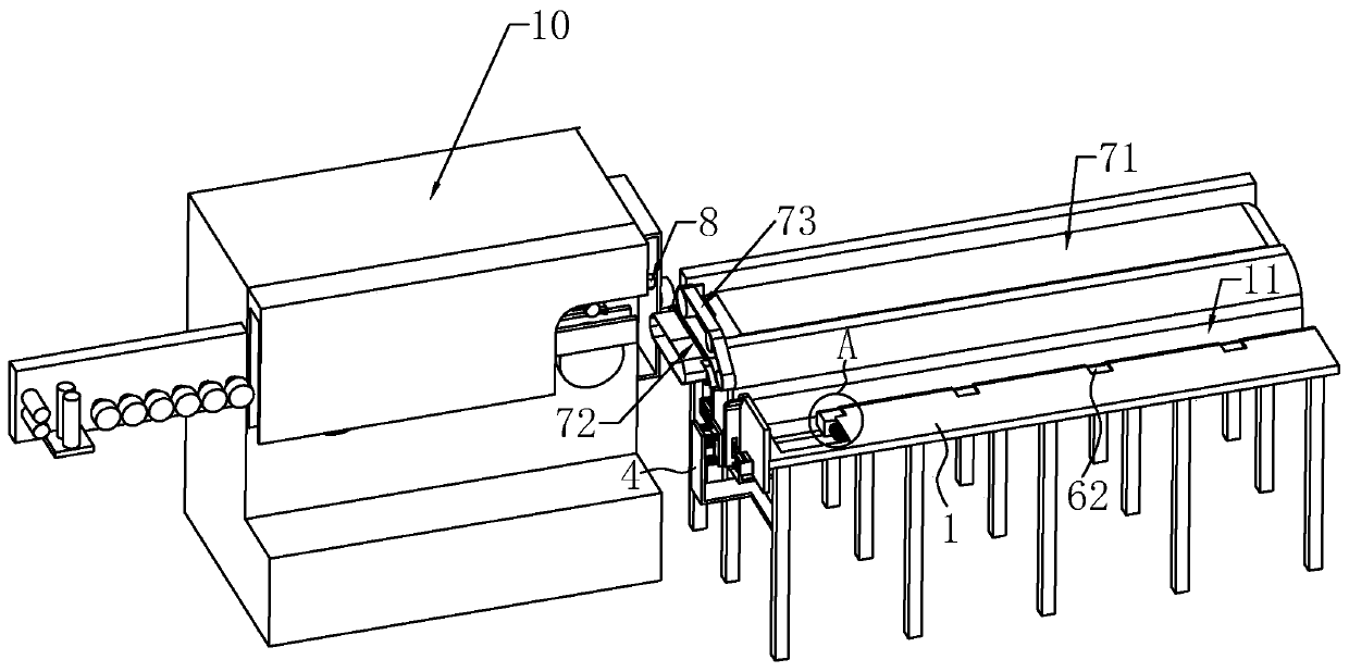
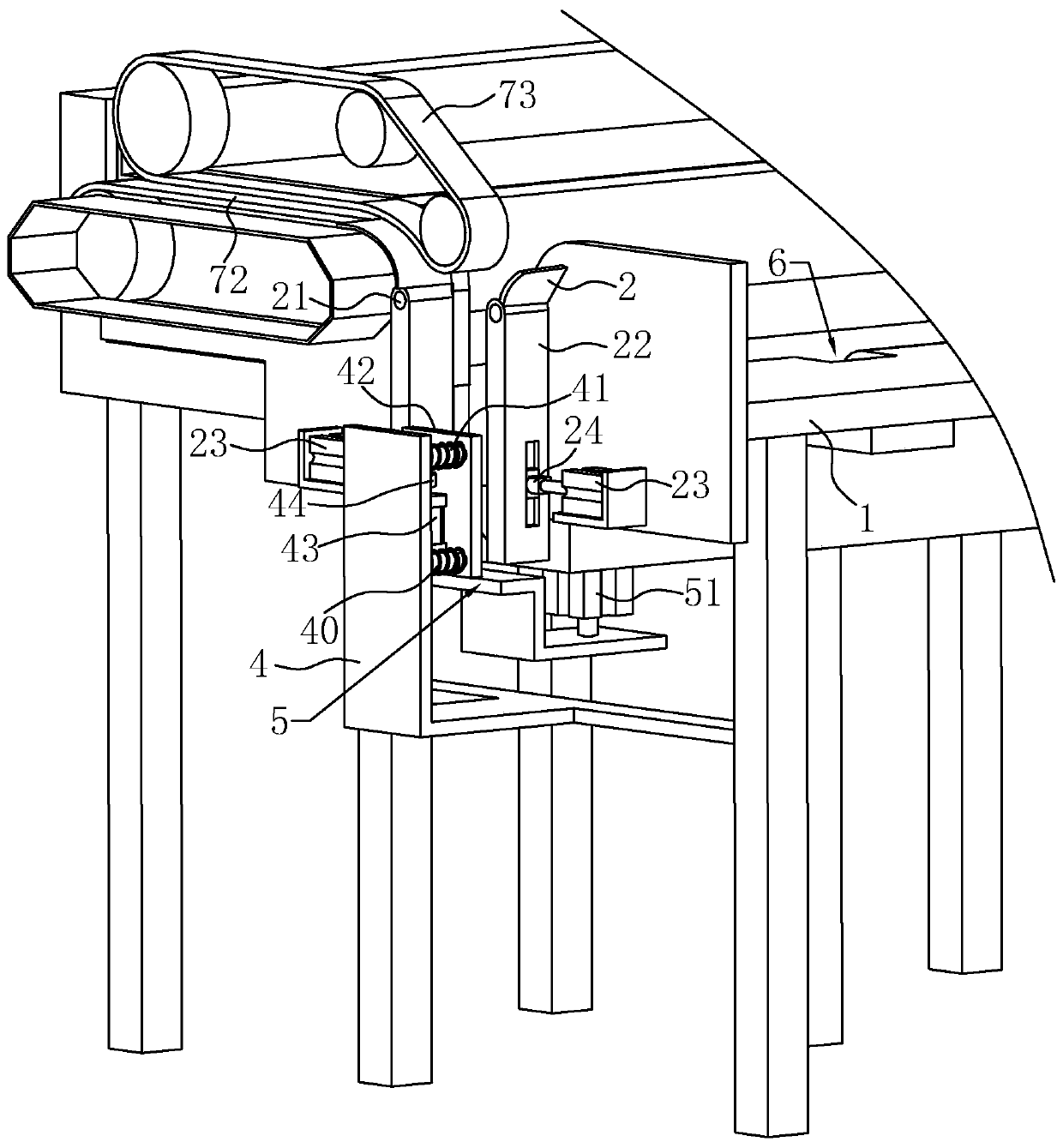
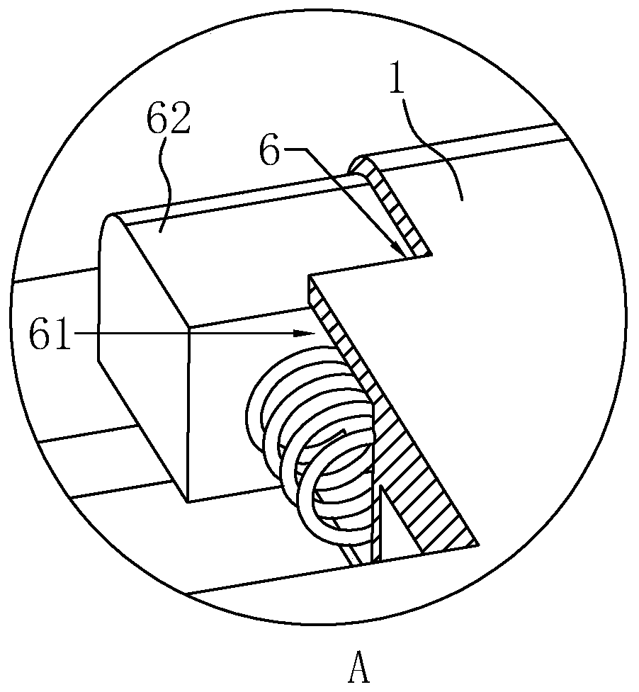
[0040] Embodiment 1: A kind of automatic wire cutting machine for automobile wiring harness, such as Figure 1 to Figure 3As shown, a first conveying device is installed on the workbench 1, and the first conveying device is a first conveyor belt 71, and the first conveyor belt 71 is close to the discharge end of the wire cutting machine 10. When the wire cutting machine 10 is working, The staff puts the wire into the wire cutting machine 10, and the two rows of conveying rollers in the wire cutting machine 10 will automatically convey the wire to the discharge port of the wire cutting machine 10 under the drive of the power mechanism, and the wire cutting machine 10 The wire delivered from the outlet will continue to be transported through the first conveyor belt 71 .
[0041] In this embodiment, a second conveying device is provided on the side of the workbench 1 close to the wire cutting machine 10, the conveying direction of the second conveying device is perpendicular to t...
Embodiment 2
[0061] Embodiment 2: as Figure 4 As shown, the difference from Embodiment 1 lies in the difference of the drive assembly. In this embodiment, the drive assembly includes: a motor 3 installed on the outside of the workbench 1, the motor 3 is located on both sides of the two movable plates 22, and on the Rotating rod 31 is installed on the output shaft of motor 3, and the extension direction of rotating rod 31 is perpendicular to the conveying direction of the first delivery device, and on the end of rotating rod 31, beating ball 32 is also installed, and beating ball 32 adopts rubber Made of material.
[0062] When the motor 3 is turned on, it can drive the rotating rod 31 to rotate. During the rotation, the rotating rod 31 can drive the knocking ball 32 to knock the outer walls of the movable plate 22, so that the movable plate 22 can rotate and swing around the rotating shaft 21. Through this solution, it is also very convenient to drive the movable plate 22 to swing, so th...
PUM
 Abstract
Description
Claims
Application Information
 - R&D
- Intellectual Property
- Life Sciences
- Materials
- Tech Scout
- Unparalleled Data Quality
- Higher Quality Content
- 60% Fewer Hallucinations
Browse by: Latest US Patents, China's latest patents, Technical Efficacy Thesaurus, Application Domain, Technology Topic, Popular Technical Reports.
© 2025 PatSnap. All rights reserved.Legal|Privacy policy|Modern Slavery Act Transparency Statement|Sitemap|About US| Contact US: help@patsnap.com


