A fully automatic fixed-range drilling device and method for cylindrical pins

A cylindrical pin, fully automatic technology, used in positioning devices, feeding devices, clamping devices, etc., can solve the problems of complex structure, area consumption, difficult maintenance, etc., to simplify the device structure, improve processing efficiency, and simplify positioning steps. Effect

Active Publication Date: 2021-06-01
HUBEI YIDU YUNJI MEC & ELEC CO LTD
View PDF0 Cites 0 Cited by
  • Summary
  • Abstract
  • Description
  • Claims
  • Application Information

AI Technical Summary

Problems solved by technology

However, in order to realize this process, the existing fixtures are not only complicated in structure, but also difficult to repair after failure.
For the fixed-range processing part, CNC machine tools are now mostly used for processing, which occupies a large area in the entire automatic line and consumes considerable cost. It is not the best choice for "high quality, high efficiency, and low cost".

Method used


Image

  • A fully automatic fixed-range drilling device and method for cylindrical pins
  • A fully automatic fixed-range drilling device and method for cylindrical pins
  • A fully automatic fixed-range drilling device and method for cylindrical pins

Examples


Embodiment 1

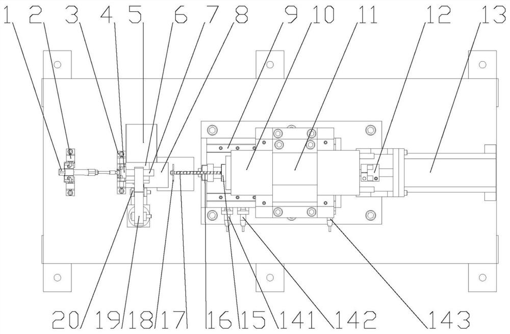
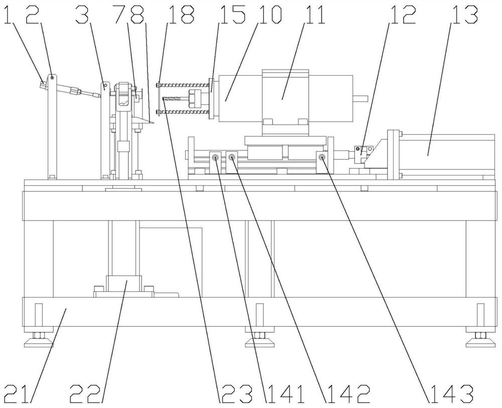
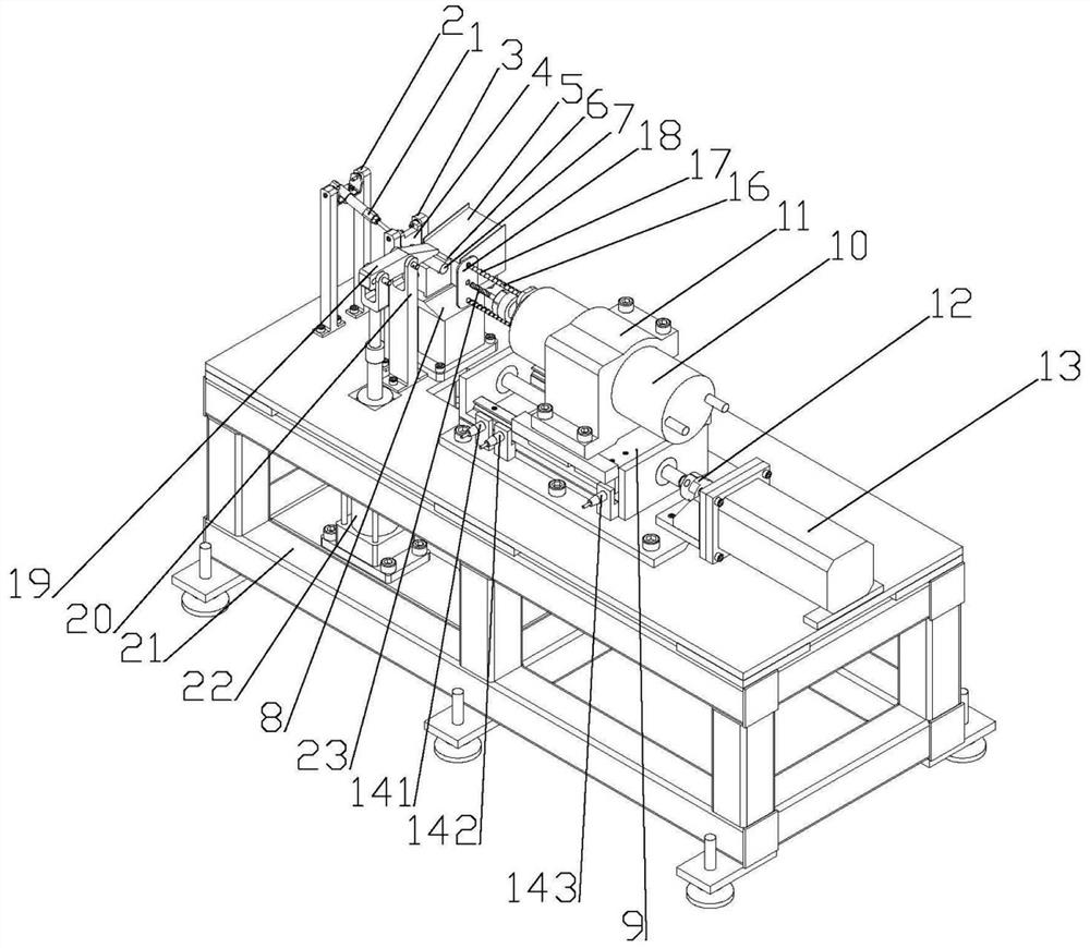
[0030] see Figure 1-3 , a full-automatic cylindrical pin fixed-range drilling device, which includes a frame 21, a V-shaped block 6 is fixedly installed on the top middle part of the frame 21, and a V-shaped block 6 is installed on one axial end of the V-shaped block 6 for The positioning and unloading device for positioning and unloading the cylindrical pin to be processed is equipped with a drilling positioning device for drilling and auxiliary positioning at the other end of the axial direction. The radial ends of the V-shaped block 6 are respectively installed with useful The feeding chute 5 for feeding and the clamping device for compressing the cylindrical pin to be processed. The drilling device adopting the above-mentioned structure can be used for the automatic drilling operation of the cylindrical pin, which can realize the automatic loading of the cylindrical pin 7 to be processed, and can realize its automatic positioning and clamping after loading, and after posi...

Embodiment 2

[0039] The method for processing cylindrical pins with a fixed-range drilling device for fully automatic cylindrical pins is characterized in that it comprises the following steps:

[0040] Step 1: Roll the cylindrical pin 7 to be processed to the V-shaped block 6 along the feeding slide 5;

[0041]Step 2: The positioning cylinder 1 pushes the positioning door panel 4 to close, and the driving motor 13 drives the screw nut slide table 9 to make the electric spindle 10 and the spring push plate 18 approach the cylindrical pin 7 to be processed until the spring push plate 18 pushes the cylindrical pin 7 to be processed Make its other end contact the positioning door panel 4;

[0042] Step 3: When the screw nut slide table 9 reaches the second proximity switch 142, the slide table stops moving forward, and the clamping cylinder 22 uses the lever principle to push the weight 19 to clamp the cylindrical pin 7 to be processed;

[0043] Step 4: Slide table 9 advances again, drives k...


PUM


Abstract

The invention provides a fully automatic fixed-range drilling device and method for cylindrical pins, which includes a frame, a V-shaped block is fixedly installed in the middle part of the top of the frame, and one axial end of the V-shaped block is installed with a useful For the positioning and unloading device for positioning and unloading the cylindrical pin to be processed, a drilling positioning device for drilling and auxiliary positioning is installed at the other end of the axial direction. The radial ends of the V-shaped block are respectively installed with useful The feeding chute for feeding and the clamping device for pressing the straight pins to be processed. This device can perform axial fixed-distance drilling on cylindrical pins, and at the same time meet the requirements of accurate automatic positioning and clamping of parts before processing and automatic clamping and unloading after processing.

Description

technical field [0001] The invention relates to the field of automatic manufacturing systems, in particular to a fully automatic fixed-stroke drilling device and method for cylindrical pins. Background technique [0002] In the automatic production line, the process of batch machining the axial holes of cylindrical pin parts is completed without human intervention. At this time, it is necessary to design an efficient and reliable device to complete the positioning and clamping of the parts from before processing to after processing. The whole process of unclamping and unloading. However, in order to realize this process, the existing clamps are not only complex in structure, but also difficult to maintain after failure. For the fixed-range processing part, CNC machine tools are now mostly used for processing, which occupies a large area in the entire automatic line and consumes considerable cost. It is not the best choice to meet "high quality, high efficiency, and low cost...

Claims


Application Information

Patent Timeline
Patent Type & Authority Patents(China)
IPC IPC(8): B23C3/00B23Q3/08B23Q3/18B23Q5/40
CPCB23C3/00B23Q3/062B23Q3/08B23Q3/18B23Q5/40B23Q2703/04
Inventor 张明松常晟庄桥
Owner HUBEI YIDU YUNJI MEC & ELEC CO LTD
Why Eureka
Try Eureka