Second transfer belt turning device
A technology of turning device and belt, applied in the directions of transportation and packaging, conveyors, conveyor objects, etc., can solve the problems of inability to realize turning, structural limitations, and unusable secondary loads, and achieve the effect of ensuring normal operation.
- Summary
- Abstract
- Description
- Claims
- Application Information
AI Technical Summary
Problems solved by technology
Method used
Image
Examples
Embodiment 1
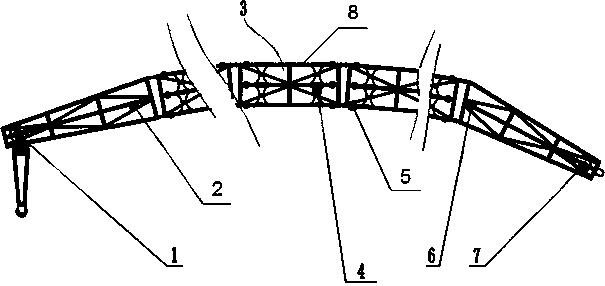
[0022] like figure 1 As shown, a second belt turning device includes a tail frame 2, several intermediate frames 3 and a head frame 6, an electric drum 7 is installed on the head frame 6, and a steering drum 1 is installed on the tail frame 2. Said middle frame 3 is composed of turning sub-frame 8 hinged connections, and the two ends of middle frame 3 are respectively hinged with nose frame 6 and tail frame 2; said turning sub-frame 8 has at least four articulated joints 81, respectively arranged on The upper and lower parts of the two ends of the turning subframe 8, the belt is installed on the electric drum 7 and the steering drum 1, the load and return belts are located in the turning subframe 8, and the belt roller 5 and the limit turning are set in the turning subframe 8. roll 4.
[0023] The structure to realize turning is on the hinged turning subframe. Due to the design of hinge points, each hinge point can realize a certain turning angle, and multiple turning subfram...
Embodiment 2
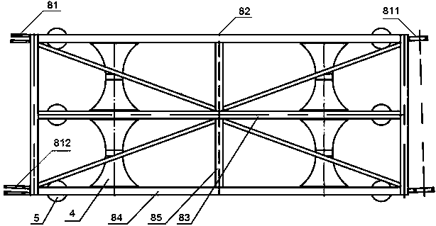
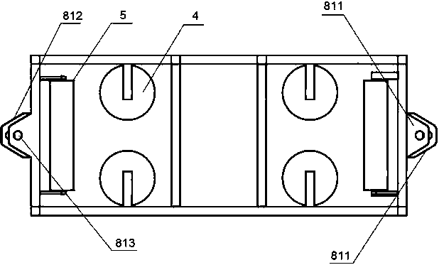
[0025] As a kind of technical scheme of embodiment 1, such as figure 2 , 3 As shown in , 4, the turning subframe 8 includes a frame body, and hinged joints 81 are arranged on the upper and lower parts of the end faces of both ends of the frame body.
[0026] The articulated joint 81 is two plugs 811 and two plugs 812, wherein the plug 811 is a plate with a hinge hole 813, the plug 812 is two plates with a hinge hole 813, and the two plates of the plug 812 are directly connected to each other. There is an insertion space for the plug board, which is hinged through the hinge hole 813 .
[0027] The hinge holes of the hinged joint 81 located on the upper plug and the lower plug are not on the same axis.
[0028] The hinge joint 81 is located at the center of the hinge hole of the upper plug and the center of the hinge hole of the lower plug, and the included angle between the end surface of the frame body is greater than 0° and less than 60°.
[0029] The included angle betwe...
Embodiment 3
[0032] As a kind of technical scheme of embodiment 1, such as figure 2 , 3 , 4, the frame body includes an upper frame 82, an intermediate frame 83 and a lower frame 84, and a connecting rod 85 connecting the upper frame 82, the intermediate frame 83 and the lower frame 84, and the upper frame 82, the intermediate frame 83 and the lower frame 84 are equipped with some idler rollers 5, between the upper frame 82 and the middle frame 83, and between the middle frame 83 and the lower frame 84, several concave arc-shaped limit turning rollers 4 are installed, and the belt is positioned on the idler rollers. on, and between the limit turning rollers 4.
[0033] The supporting rollers 5 are provided with six, and two are respectively arranged at the two ends of the upper frame 82, the intermediate frame 83 and the lower frame 84; In the frame body between the belt rollers 5.
[0034] The ratio of the diameter of the circles at both ends of the limiting turning roller 4 to the mi...
PUM
 Abstract
Description
Claims
Application Information
 - R&D
- Intellectual Property
- Life Sciences
- Materials
- Tech Scout
- Unparalleled Data Quality
- Higher Quality Content
- 60% Fewer Hallucinations
Browse by: Latest US Patents, China's latest patents, Technical Efficacy Thesaurus, Application Domain, Technology Topic, Popular Technical Reports.
© 2025 PatSnap. All rights reserved.Legal|Privacy policy|Modern Slavery Act Transparency Statement|Sitemap|About US| Contact US: help@patsnap.com


