Seismic reflected wave slope and gravity anomaly data joint inversion method

A gravity anomaly and seismic reflection technology, applied in seismology, seismic signal processing, geophysical measurement, etc., can solve the problems of large influence of subjective factors, empirical relationship of physical properties contrary to underground, inversion depth dependent on offset, etc., to achieve weakening Ambiguity, avoiding multi-solution problems, excellent effect

Active Publication Date: 2020-06-02
OCEAN UNIV OF CHINA
View PDF5 Cites 6 Cited by
  • Summary
  • Abstract
  • Description
  • Claims
  • Application Information

AI Technical Summary

Problems solved by technology

In the early joint inversion, the seismic data mainly played the role of controlling the horizon and guiding the separation of the gravity field, using the gravity data to supplement the places where the seismic reflection is unclear, and obtaining the structural distribution characteristics and interface extension information that cannot be determined only by the seismic data , this method is greatly affected by subjective factors; later, the joint inversion of post-stack seismic and gravity data appeared, which will directly introduce the deviation of the post-stack section into the inversion results, and this error is concealed; later developed the The joint inversion of first arrival travel time and gravity data of pre-stack earthquakes, this method only uses the travel time information of earthquakes, cannot well resolve the ambiguity between formation depth and velocity, and the inversion depth is heavily dependent on offset
In addition, the joint inversion of severe earthquakes usually imposes constraints on the physical property relationship. The disadvantage of this method is that the explicit physical property empirical relationship may violate the real situation of the subsurface

Method used


Image

  • Seismic reflected wave slope and gravity anomaly data joint inversion method
  • Seismic reflected wave slope and gravity anomaly data joint inversion method
  • Seismic reflected wave slope and gravity anomaly data joint inversion method

Examples


Embodiment Construction

[0052] In order to make the purpose and technical solution of the present invention clearer, the present invention will be further described in detail below in conjunction with the accompanying drawings.

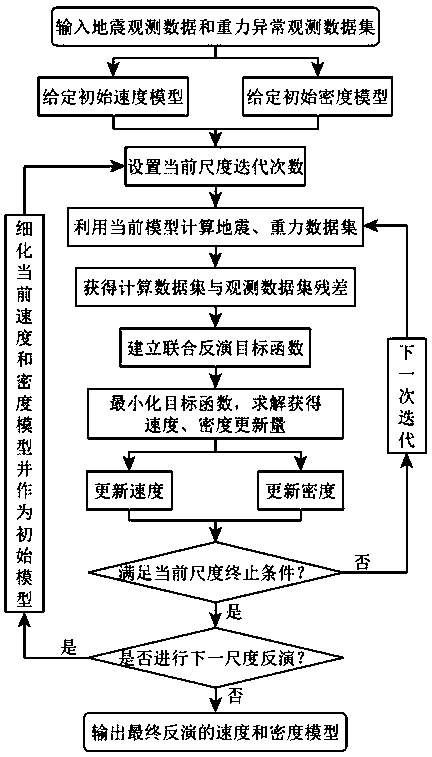
[0053] Such as figure 1 As shown, a joint inversion method of seismic reflection travel time, slope and gravity anomaly data according to the present invention comprises the following steps:

[0054] Step 1: Input seismic observation data and gravity anomaly observation data set:

[0055] S1: Obtain the position of the shotgun inspection point from the seismic record, pick up the reflected wave travel time and travel time slope, and form a seismic observation data set: , where s and r represent the abscissa and ordinate positions of the shot point and the receiver point respectively; and represent the traveltime slopes at the shot point and the receiving point, respectively; represents the travel time of the reflected wave; N is the number of data sets picked up;

...


PUM


Abstract

The invention relates to a seismic reflected wave slope and gravity anomaly data joint inversion method, and belongs to the field of seismic and gravity data joint inversion of geophysical exploration. The method comprises the following steps of inputting the seismic observation data and a gravity anomaly observation data set; giving an initial model; calculating the seismic and gravity data setsby utilizing a current model; obtaining a residual error between a calculation data set and the observation data set; establishing a joint inversion objective function; solving to obtain the speed and density update amounts; updating the model; and terminating iteration and outputting a final result. According to the method, the seismic wave slope and the gravity anomaly data are utilized at thesame time, under the constraint of structural similarity, the multi-scale strategy iteration is adopted to calculate the update amount of a speed and density difference model, and finally a speed-density model with a similar structure is obtained at the same time. The joint inversion method can effectively reduce the multi-solution problem of the single-type data inversion, and the speed-density model with higher precision is obtained.

Description

technical field [0001] The invention relates to a joint inversion method of seismic reflection wave slope and gravity anomaly data, which belongs to the field of joint inversion of seismic and gravity data in geophysical exploration. Background technique [0002] There are obvious differences in the velocity and density parameters of different lithologic formations underground, and only a limited understanding of the subsurface structure can be obtained based on a single observation data from seismic inversion or gravity inversion alone, and this understanding is often difficult to withstand. As another test of observational data, a single method has certain one-sidedness and limitations. [0003] The joint inversion of severe earthquakes is the key to solve this problem. In the early joint inversion, the seismic data mainly played the role of controlling the horizon and guiding the separation of the gravity field, using the gravity data to supplement the places where the s...

Claims


Application Information

Patent Timeline
IPC IPC(8): G01V1/28G01V1/30
CPCG01V1/282G01V1/303
Inventor 刘洁张建中
Owner OCEAN UNIV OF CHINA
Why Eureka
Try Eureka