
Fixing mechanism used for ice surface punching device

A technology of punching device and fixing mechanism, which is applied in fishing accessories, applications, fishing, etc. It can solve the problems of poor stability level safety, scratch damage, slipping and falling of operators, and achieve extended length, Effect of improving stability and reliability, improving safety and stability

Active Publication Date: 2020-06-05
山东宝成制冷设备有限公司
View PDF5 Cites 1 Cited by
  • Summary
  • Abstract
  • Description
  • Claims
  • Application Information

AI Technical Summary

Problems solved by technology

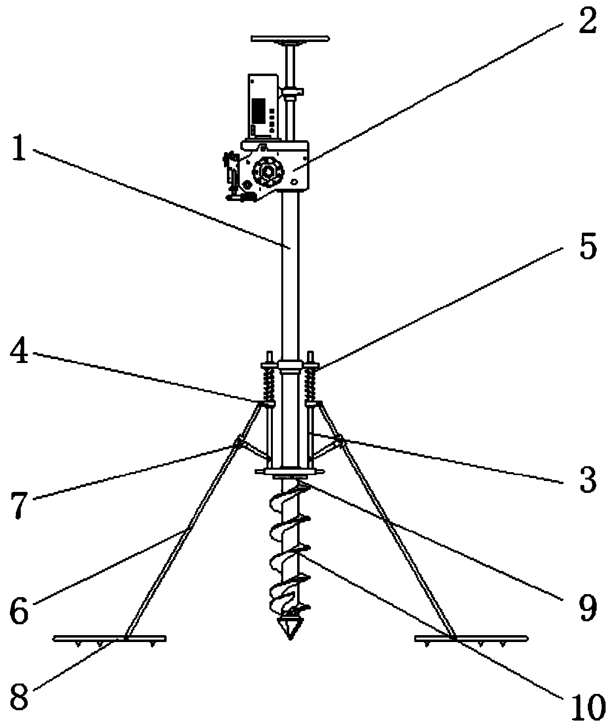
[0005] The invention provides a fixing mechanism for an ice surface punching device, which has the advantages of high safety and stability, convenient use and simple operation, and solves the problem that the existing ice surface punching device is a set of simple The auger drill rod is equipped with a power output mechanism, and the operator's hands are completely relied on to control the balance of the entire drilling device during the drilling process. However, due to the small friction on the ice surface, the operator will It will be subjected to the reverse force of the auger rod, which will cause the operator to slip and fall easily, resulting in the contact between the auger rod and the human body in the working state, and then causing scratch damage to the operator's limbs Phenomenon, the problem of poor stability level security

Method used


Image

  • Fixing mechanism used for ice surface punching device
  • Fixing mechanism used for ice surface punching device
  • Fixing mechanism used for ice surface punching device

Examples


Embodiment Construction

[0020] The following will clearly and completely describe the technical solutions in the embodiments of the present invention with reference to the accompanying drawings in the embodiments of the present invention. Obviously, the described embodiments are only some, not all, embodiments of the present invention. Based on the embodiments of the present invention, all other embodiments obtained by persons of ordinary skill in the art without making creative efforts belong to the protection scope of the present invention.

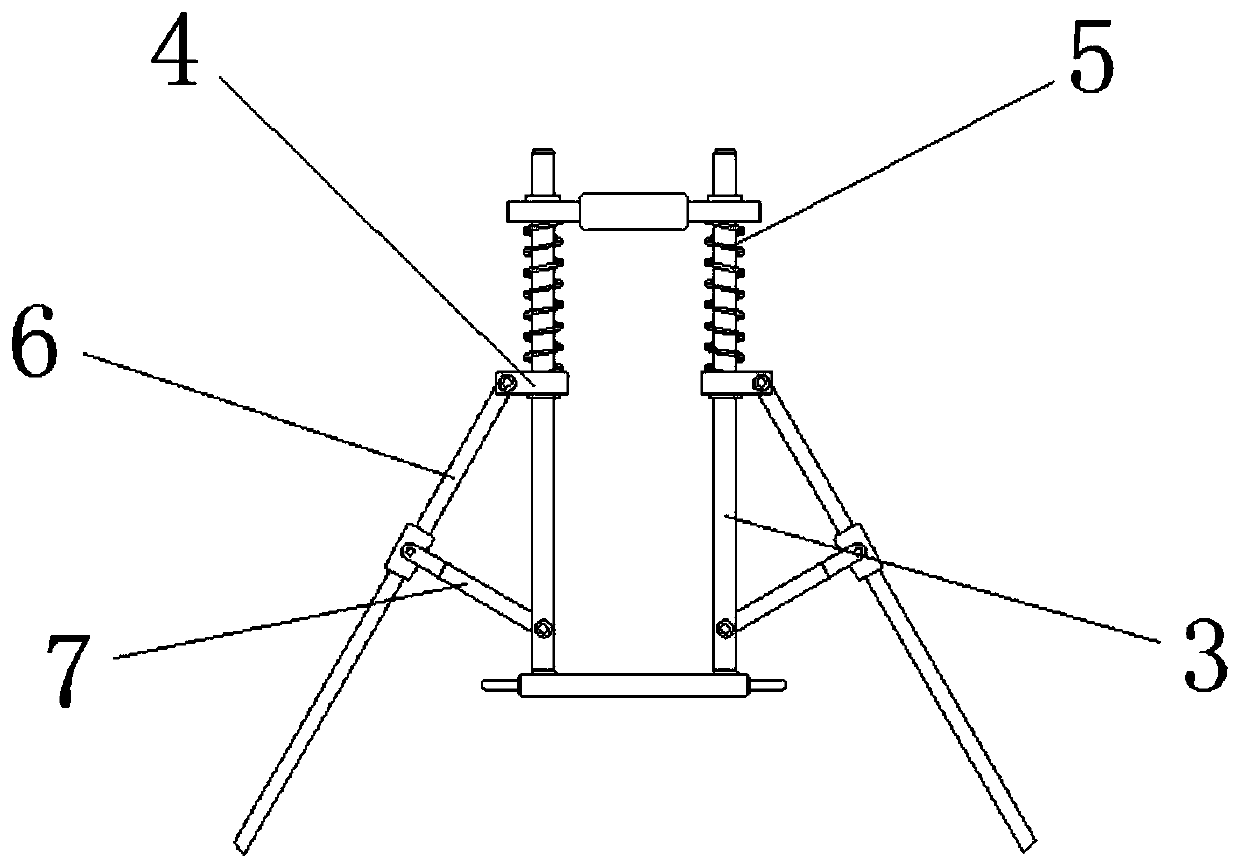
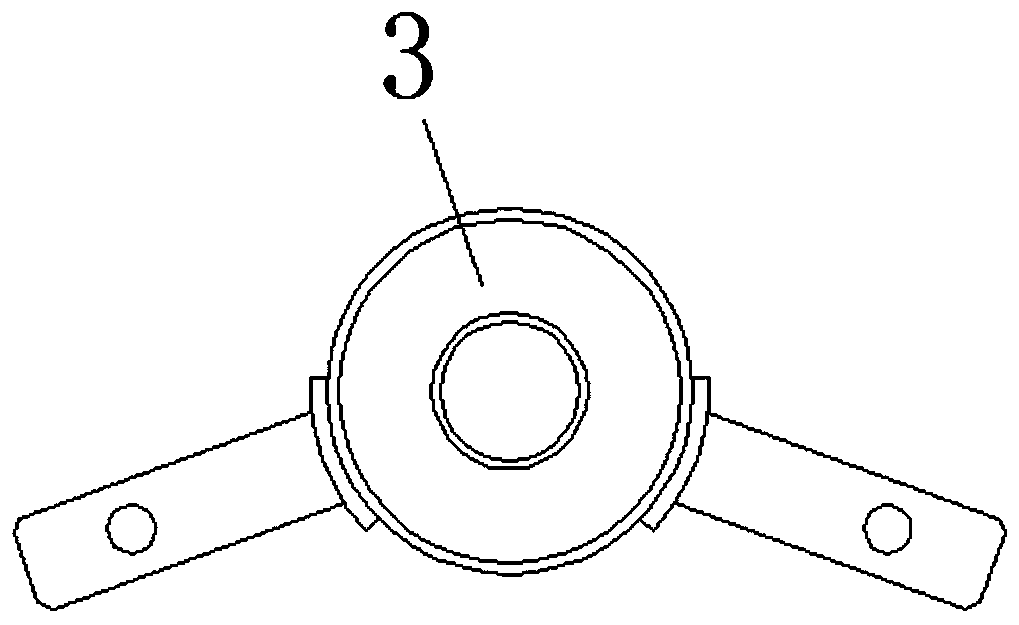
[0021] see Figure 1-3 , a fixing mechanism for the ice surface punching device, comprising a transmission link 1, the top of the transmission link 1 is provided with a drive mechanism 2, the middle part of the outer surface of the transmission link 1 is movably sleeved with a fixed bracket 3, and fixed The outer surfaces of both ends of the bracket 3 are movably socketed with movable sliding sleeves 4, and the outer surfaces of the two ends of the fixed brack...


PUM


Abstract

The invention relates to the technical field of ice surface drilling equipment, and discloses a fixing mechanism used for an ice surface punching device. The fixing mechanism used for the ice surfacepunching device comprises a transmission connection rod, wherein a driving mechanism is arranged at the top end of the transmission connection rod, the middle portion of the outer surface of the transmission connection rod is movably sleeved with a fixing support, outer surfaces of both ends of the fixing support are movably sleeved with movable sliding sleeves, the portions, located under the movable sliding sleeves, on the outer surfaces of the two ends of the fixing support are movably sleeved with reset springs, and one end of each movable sliding sleeve is movably connected with a corresponding supporting connection rod. According to the fixing mechanism used for the ice surface punching device, by arranging broken-line-type structures on two sides of the fixing support and by settingan included angle of the broken-line-type structures on the two sides of the fixing support, when an operator bends down to punch holes, positions of the operator and the transmission connection rodcan be staggered mutually, and thus the phenomenon of mutual disturbance of the operator and the transmission connection rod when the operator punches holes in an ice surface is avoided, so that the stability and the reliability of the fixing mechanism are further improved.

Description

technical field [0001] The invention relates to the technical field of ice surface drilling equipment, in particular to a fixing mechanism for an ice surface drilling device. Background technique [0002] Punching holes on the ice surface is a common operation in the fishery industry in the cold northern winter. On the one hand, the hole in the ice surface can be used for fishing operations, and on the other hand, the water source below the ice surface can be in contact with the air. In order to increase the oxygen content of the water flow, and thus prevent the long-term frozen lake water source from the lack of oxygen and fish death. [0003] At present, the existing ice surface drilling devices are all a group of simple auger rods equipped with a power output mechanism, which completely rely on the operator's hands to control the balance of the entire drilling device during the drilling process. The friction force on the ice surface is small, and the operator will be sub...

Claims


Application Information

Patent Timeline
IPC IPC(8): A01K97/01
CPCA01K97/01
Inventor 李斌
Owner 山东宝成制冷设备有限公司
Learn More