Spatial three-freedom parallel robot mechanism

A degree of freedom and robot technology, applied in the direction of manipulators, manufacturing tools, etc., can solve the problems of low precision, low rigidity, and difficult motion determination of end parts, and achieve the effects of wide application prospects, low motion quality, and high dynamic performance

Inactive Publication Date: 2003-06-25
TSINGHUA UNIV
View PDF0 Cites 6 Cited by
  • Summary
  • Abstract
  • Description
  • Claims
  • Application Information

AI Technical Summary

Problems solved by technology

The tandem type is an open chain in which the rods are connected sequentially through kinematic pairs. This type of robot has a large working space and high flexibility. The disadvantages are: ①The accuracy of the end piece is very low due to the accumulation of errors of each rod; ②Stiffness Low; ③ large inertia, poor dynamic performance
Among the 40% of the existing three-degree-of-freedom parallel mechanisms, some are planar mechanisms, some are spherical mechanisms, some are three-dimensional purely moving mechanisms, and some are spatial mechanisms whose motion is difficult to determine at different points in space
For example, the 3-RPS robot mechanism, which has been studied for a long time at home and abroad, was proposed in 1983. Th

Method used


Image

  • Spatial three-freedom parallel robot mechanism
  • Spatial three-freedom parallel robot mechanism
  • Spatial three-freedom parallel robot mechanism

Examples


Example Embodiment

[0018] Example 1: One of the three-degree-of-freedom spatial parallel robot mechanism

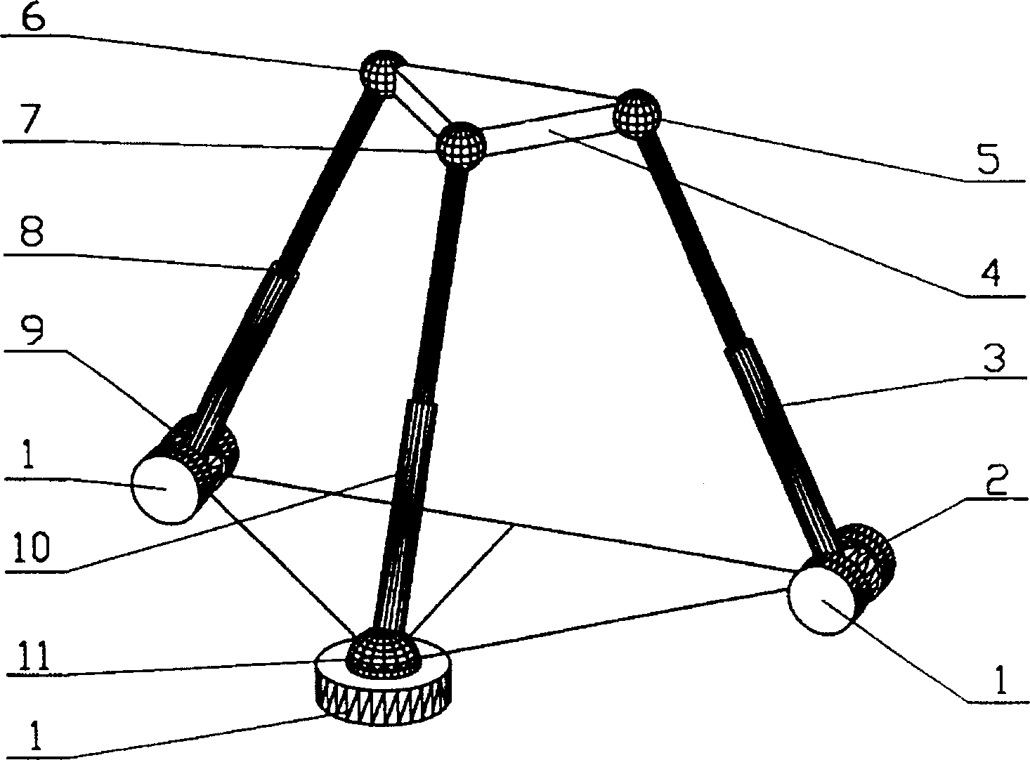
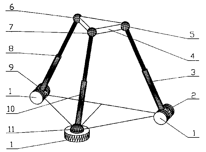
[0019] The overall structure of this embodiment is as figure 1 As shown, the motion table 4 of the mechanism is connected to the frame 1 through three telescopic connecting rods 3, 8, 10, wherein the connecting rods 3, 8 are connected to the motion pair at one end of the motion table 4 by a three-degree-of-freedom spherical hinge 5. 6. The kinematic pairs connected to the frame 1 at the other end are rotating pairs 2 and 9; the kinematic pairs of the connecting rod 10 connecting the motion table 4 and the frame 1 are Hooke hinges 7 and 11, respectively. The movement platform 4 realizes the two-dimensional movement of the plane where the connecting rods 3 and 8 are located and the rotation of the hinges 5 and 6 in a three-degree-of-freedom space movement through the movement of the three telescopic connecting rods 3, 8, 10.

Example Embodiment

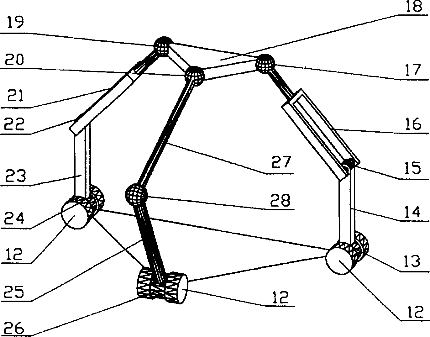
[0020] Example 2: Spatial three-degree-of-freedom parallel robot mechanism II

[0021] The overall structure of this embodiment is as figure 2 As shown, the movement table 18 of the mechanism respectively passes through the first and second branches formed by the connecting rods 16, 21, the connecting rods 14, 23, and the third branch and the frame formed by the connecting rod 27 and the connecting rod 25. 12-phase connection. The connecting rods 16, 21 are connected to the sports platform 18 by three-degree-of-freedom ball joints 17, 19 at one end, and the other ends are connected with the connecting rods 14, 23 through the rotating pairs 15, 22; the connecting rod 27 connects the sports platform 18 and the connecting rod. The movement pairs of the frame rod 25 are Hooke hinges 20 and 28, respectively; the connecting frame rods 14, 23, 25 are connected to the frame through the rotating pairs 13, 24, and 26, respectively. The movement table 18 realizes the two-dimensional movement...


PUM


Abstract

The present invention belongs to the field of industrial robot. The robot mechanism consists of one frame, one moving stage and three branches to connect the moving stage to the frame to form a parallel closed loop structure. Of the branches, each of two contains two single-freedom motion pairs and one ball articulation, and the third contains one single-freedom motion pair and one Hooke. The ends containing the moving stage and the frame are not collinear. The robot mechanism of the present invention combines the spatial shift and rotation and has the advantages of high rigidity, high accuracy, low motion mass high dynamic performance, very easy kinematics solution, etc.2

Description

Technical field [0001] The invention belongs to the field of industrial robots, and particularly relates to a spatial three-degree-of-freedom parallel robot mechanism with two-dimensional movement and one-dimensional rotation. Background technique [0002] There are two types of mechanisms in existing robots in service with roboticized tasks: series and parallel. The tandem type is an open chain in which the rods are connected in sequence through the motion pair. This type of robot has a large working space and high flexibility. The disadvantages are: ①The accuracy of the end pieces is very low due to the accumulation of errors of the rods; ②Rigidity Low; ③Large inertia and poor dynamic performance. Therefore, tandem robots are not suitable for operations that require high positioning and force control accuracy. In order to avoid such shortcomings, the robot mechanism can be parallel. [0003] The parallel robot mechanism is a closed-loop mechanism, and its moving platform or ter...

Claims


Application Information

Patent Timeline
IPC IPC(8): B25J11/00
Inventor 刘辛军汪劲松段广洪
Owner TSINGHUA UNIV
Why Eureka
Try Eureka