Continuous preparation device for metal mobile phone shells

A technology for a mobile phone casing and a preparation device is applied in the field of continuous preparation devices for metal mobile phone casings, and can solve the problems of simple processing methods for mobile phone casings, inability to meet the needs of users, and inability of continuous preparation by the manufacturing method.

Pending Publication Date: 2020-06-05
江苏杰邦电子科技有限公司
View PDF0 Cites 0 Cited by
  • Summary
  • Abstract
  • Description
  • Claims
  • Application Information

AI Technical Summary

Problems solved by technology

[0003] In view of the above problems, the present invention proposes a continuous preparation device for metal mobile phone shells, which has solved the problem that the existing mobile phone s

Method used


Image

  • Continuous preparation device for metal mobile phone shells
  • Continuous preparation device for metal mobile phone shells

Examples


Example Embodiment

[0016] Example 1:

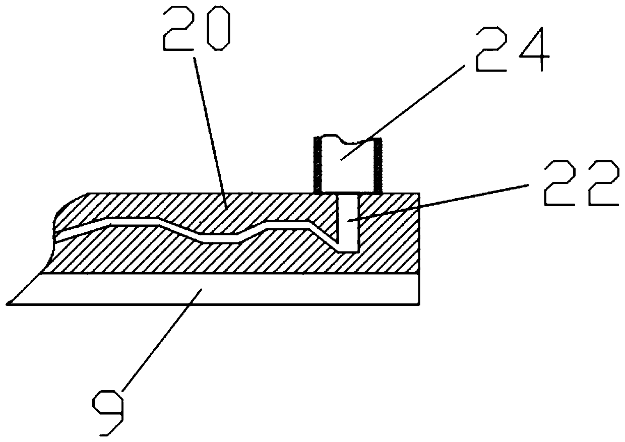
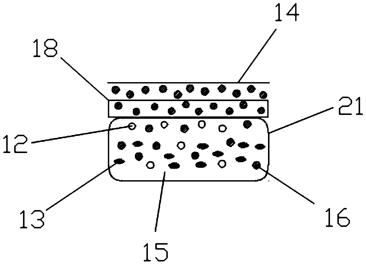
[0017] according to Figure 1-3 As shown, this embodiment proposes a continuous preparation device for a metal mobile phone shell, which includes a stirring motor 2, a die-casting cavity 19, and a support frame 17. The stirring motor 2 is provided with a feeding port 1 on the left side, and the feeding port 1 is installed in the melting box 3. On the upper side, the melting box 3 is provided with a melting box rack 4, and the lower side of the melting box rack 4 is fixedly connected to the support rack 17, the right side of the support rack 17 is provided with a heater 5, the heater 5 is connected to the feeding pipe 6, and the feeding pipe 6 is A solenoid valve 7 is provided. The solenoid valve 7 is connected to the die-casting cavity 19, the left side of the die-casting cavity 19 is connected to a cooling box 8, and the lower end of the cooling box 8 is provided with a coolant tank 23, which is fixedly connected to the frame 9, and the frame 9 A column 10 i...

Example Embodiment

[0023] Example 2:

[0024] according to Figure 1-3 As shown, this embodiment provides a continuous preparation device for a metal mobile phone shell, which includes a stirring motor 2, a die-casting cavity 19, and a support frame 17. The stirring motor 2 is provided with a discharge port 1 on the left side, and the discharge port 1 is installed in the melting tank 3. On the upper side, the melting box 3 is provided with a melting box rack 4, and the lower side of the melting box rack 4 is fixedly connected to the support rack 17, the right side of the support rack 17 is provided with a heater 5, the heater 5 is connected to the feeding pipe 6, and the feeding pipe 6 is A solenoid valve 7 is provided. The solenoid valve 7 is connected to the die-casting cavity 19, the left side of the die-casting cavity 19 is connected to a cooling box 8, and the lower end of the cooling box 8 is provided with a coolant tank 23, which is fixedly connected to the frame 9, and the frame 9 A column...


PUM


Abstract

The invention provides a continuous preparation device for metal mobile phone shells. The device is characterized in that by starting a stirring motor, shell metal solid pieces in mobile phone shell shapes are put into a die-casting mould from a feeding hole, and then die-casting materials, with melting points lower than that of the shell metal solid pieces, of the metal solid pieces are injectedinto the die-casting mould for die casting, so that inner surface structural parts of the mobile phone shells are made of the die-casting materials, the shell metal solid pieces are used as the outersurfaces of the mobile phone shells, and then the mobile phone shells are manufactured; and by means of the continuous preparation device for the metal mobile phone shells, raw materials in a molten state are injected into a moulding cavity, and the moulding cavity is of a multi-corner design, so that it is guaranteed that the materials generate enough deformation when passing through the mouldingcavity, grains are refined, and the metal mobile phone shells can be continuously prepared by continuously adding raw materials. According to the device, the problem that an existing mobile phone shell machining mode is simple, and the continuous preparation cannot be carried out through the manufacturing method is solved.

Description

technical field [0001] The invention relates to the technical field of preparing mobile phone casings, in particular to a continuous preparation device for metal mobile phone casings. Background technique [0002] With the rapid development of science and technology, people spend less and less energy on the trivial matters of life, and replace them with an efficient and convenient life mode. In our life, along with the wide application of 3G networks and smart phones, mobile phones have become a must for modern people to travel. Mobile phones are mobile terminals and mobile phones that can be held in our hands. Until now, mobile phones have become It is a very important tool in people's life, and it has diversified functions like a Swiss army knife and brings people a good life experience. However, the existing mobile phone shell processing method is simple, and the manufacturing method cannot be used for continuous preparation, which cannot satisfy the current user populati...

Claims


Application Information

Patent Timeline
IPC IPC(8): B22D17/02B22D19/16
CPCB22D17/02B22D19/16
Inventor 章华亮
Owner 江苏杰邦电子科技有限公司
Why Eureka
Try Eureka