
Building outer wall, auxiliary tool and mounting and dismounting method

A technology for building exterior walls and auxiliary tools, which is applied in construction, building maintenance, and building components. It can solve problems such as poor versatility and portability, large size of disassembly tools, and unstable panel structure, and achieves efficient disassembly and assembly. Good versatility and improved stability

Active Publication Date: 2020-06-05
台州市拓基科技有限公司
View PDF4 Cites 4 Cited by
  • Summary
  • Abstract
  • Description
  • Claims
  • Application Information

AI Technical Summary

Problems solved by technology

[0004] 1. Only by supporting the center position and the four corners of the panel can the panel be completely stabilized. In the above scheme, the center position of the panel is located in the circular plate-shaped frame, and the four corners are located in the four adjacent frames up, down, left, and right, so it is impossible to align the panel. Forms a stable support, so the panel structure is unstable
[0005] 2. In order to ensure the stability of the panel, the locking mechanism is close to the edge of the panel, and the disassembly tool needs to cooperate with all the locking mechanisms, so the volume of the disassembly tool needs to be close to covering the entire panel. Larger, poor versatility and portability

Method used


Image

  • Building outer wall, auxiliary tool and mounting and dismounting method
  • Building outer wall, auxiliary tool and mounting and dismounting method
  • Building outer wall, auxiliary tool and mounting and dismounting method

Examples


Embodiment Construction

[0054] The following are specific embodiments of the present invention and in conjunction with the accompanying drawings, the technical solutions of the present invention are further described, but the present invention is not limited to these embodiments.

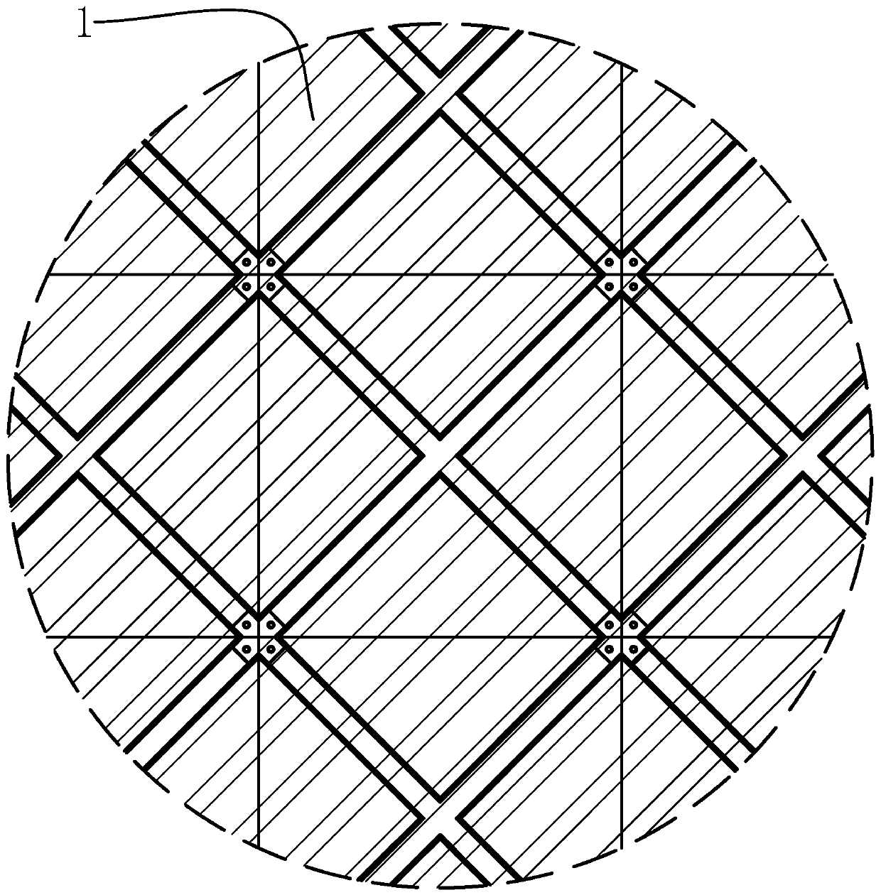
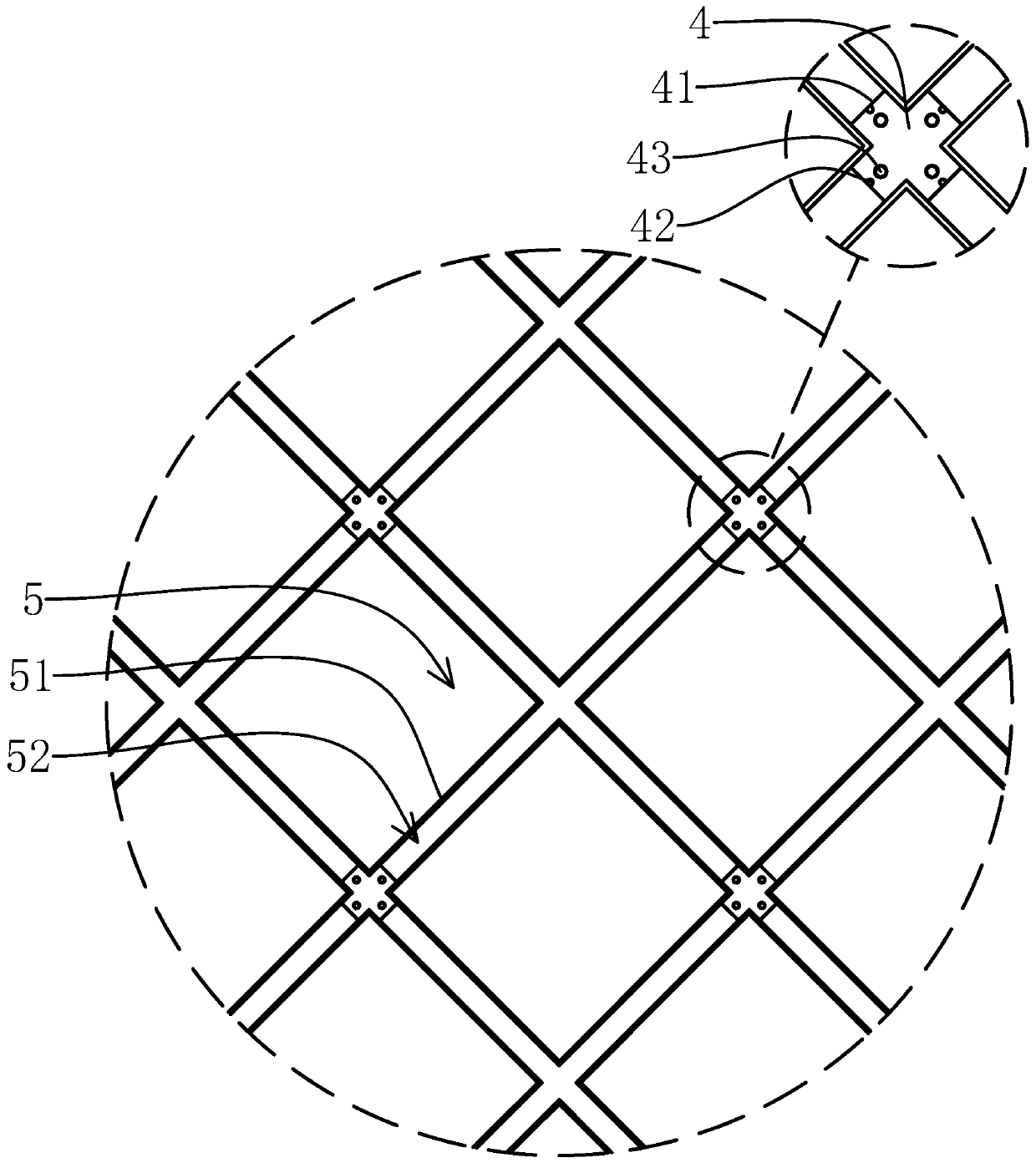
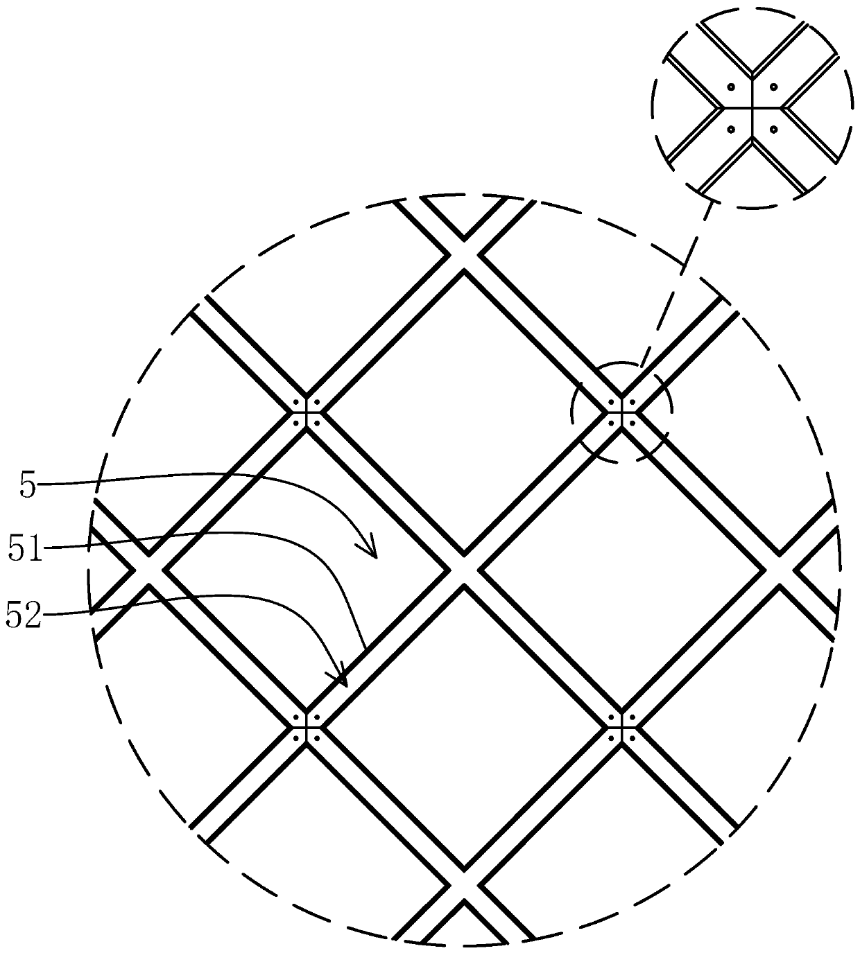
[0055] Such as Figure 1-7 As shown, a building exterior wall of the present invention includes a panel 1 of a square plate structure and a connecting skeleton of a steel structure fixed on the wall, and a connecting device is fixed on the inner surface of the panel 1, and the connecting device includes inner ends connected to form ten The four connecting bars 2 of the glyph structure, the connecting bars 2 are fixed on the inner surface of the panel 1, and the joints of the inner ends of the four connecting bars 2 are located at the center of the inner side of the panel 1, and the four outer ends of the four connecting bars 2 are respectively Near the four corners of the panel 1, a circular groove-shaped adjustment groove...


PUM


Abstract

The invention provides a building outer wall, an auxiliary tool and a mounting and dismounting method, and belongs to the field of building outer wall structures. The problems that an existing outer wall panel is unstable in structure, the auxiliary tool is large in size and not universal, and the mounting and dismounting mode is low in efficiency are solved. The building outer wall comprises a panel and a connecting framework, wherein a connecting device is fixed to the inner side face of the panel and comprises four connecting strips with the inner ends connected; the connecting strips are fixed to the inner side face of the panel; the connecting positions of the inner ends of the four connecting strips are positioned at the center position of the inner side face of the panel; the four outer ends of the four connecting strips are close to the four corner positions of the panel correspondingly; a circular groove-shaped adjusting groove is formed in the connecting position of the innerends of the four connecting strips; a circular adjusting block is movably arranged in the adjusting groove; the connecting framework comprises a plurality of connecting bases and a plurality of connecting frames; and the panel is fixed to the connecting framework through the connecting device. The panel of the building outer wall is higher in stability, the mounted panel is safe in structure, themounting and dismounting process is efficient through the auxiliary tool, and meanwhile, the universality and portability of the auxiliary tool are better.

Description

technical field [0001] The invention belongs to the technical field of building exterior wall structures, and relates to a building exterior wall, auxiliary tools and an assembly and disassembly method. Background technique [0002] In buildings, the panels are usually connected to the wall through connecting devices to form a non-load-bearing building exterior wall enclosure, which can also be called building curtain walls. According to whether the connecting devices are visible, it can be divided into open frame structure and hidden frame structure. [0003] For example, the application number is 201811086025.2, and the Chinese invention patent application titled "A high-efficiency hidden frame glass curtain wall, disassembly tool and disassembly method" installs the frame on the wall, fixes the locking structure on the back of the panel, and uses the locking mechanism and The frame fits to secure the panel to the wall. And it discloses a special disassembly tool and a sp...

Claims


Application Information

Patent Timeline
Patent Type & Authority Applications(China)
IPC IPC(8): E04B2/96E04G21/14E04G21/16E04G23/08
CPCE04B2/96E04G21/14E04G21/167E04G23/08
Inventor 张雪燕
Owner 台州市拓基科技有限公司
Learn More