House building drainage system

A technology for building drainage and housing, applied in waterway systems, roof drainage, sewer pipe systems, etc., can solve problems such as plant flooding and death, and inability to transfer rainwater.

Active Publication Date: 2020-06-05
安徽安德建筑设计有限公司
View PDF8 Cites 8 Cited by
  • Summary
  • Abstract
  • Description
  • Claims
  • Application Information

AI Technical Summary

Problems solved by technology

[0004] The above existing technical solutions have the following defects: in the existing drainage system, the rainwater discharged from the roof is used to irrigate the plants, but when there is a lot of rain in rainy days, the rainwater discharged from t

Method used


Image

  • House building drainage system
  • House building drainage system
  • House building drainage system

Examples


Embodiment Construction

[0035] The present invention will be described in further detail below in conjunction with the accompanying drawings.

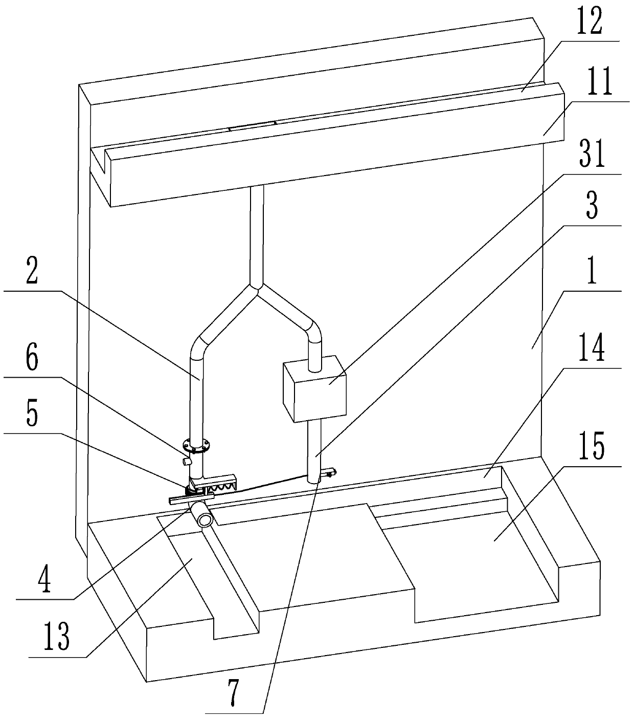
[0036] refer to figure 1 , is a building drainage system disclosed by the present invention, comprising a vertical wall 1, a parapet 11 located on the top of the wall 1, and a drainage groove 12 set on the parapet 11, and a drainage unit is arranged under the drainage groove 12 One and drainage unit two.

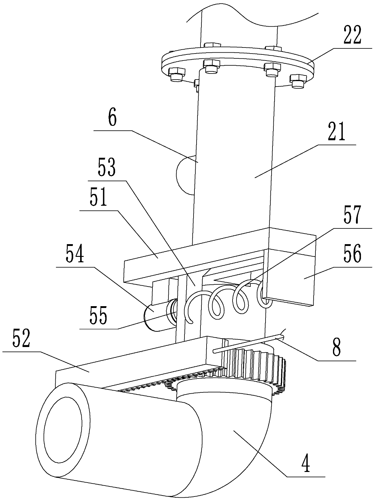
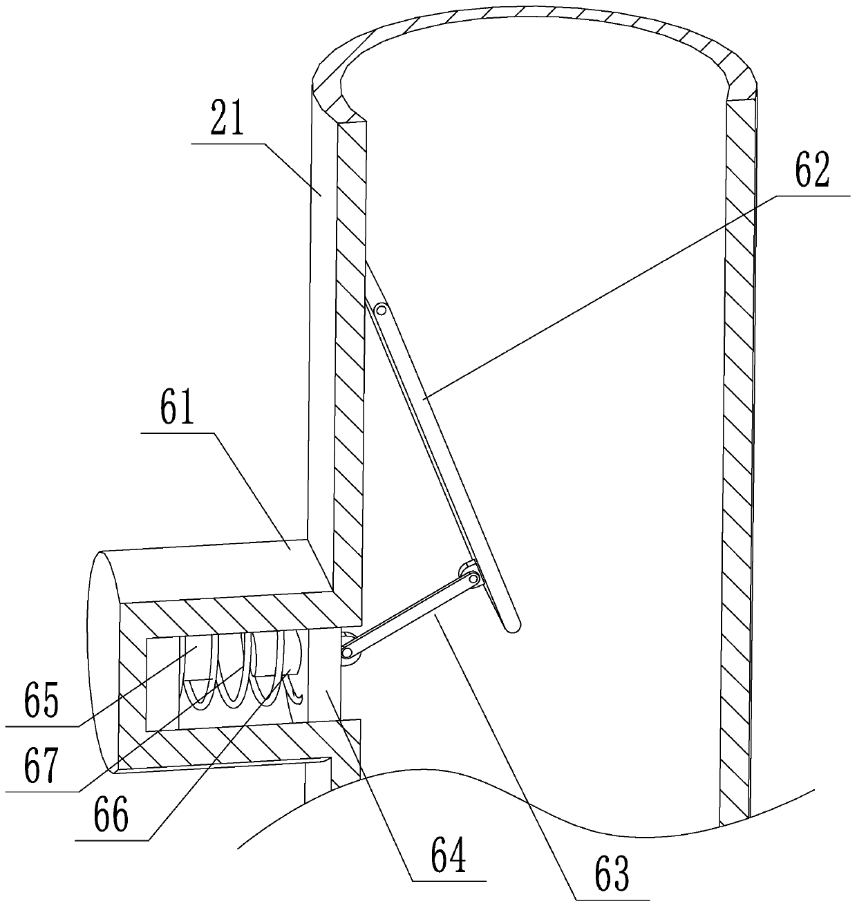
[0037] refer to figure 1 , figure 2 Drainage unit one comprises a drainpipe-2 connected to the bottom of the parapet wall 11 and the drain groove 12 and an elbow 4 connected to the bottom of the drainpipe-2, the elbow 4 is arranged in an L shape, and the drainage unit includes a water tank 31 and a water tank 31 The drainpipe 2 3 at the bottom and the top of the water tank 31 communicate with the drainpipe 1 2 through a pipeline, and the drainpipe 2 3 is provided with a valve assembly 7 . The top of the elbow 4 is sleeved on the outside of the drain pi...


PUM


Abstract

The invention relates to a house building drainage system. The system involves a vertical wall body, a parapet wall located at the top of the wall body and a drainage groove formed in the parapet wall, wherein a first drainage unit and a second drainage unit are arranged below the drainage groove, the first drainage unit involves a first drainage pipe arranged at the bottom of the parapet wall andcommunicating with the drainage groove and a bent pipe connected to the bottom of the first drainage pipe, the bent pipe is L-shaped, the second drainage unit involves a water tank and a second drainage pipe arranged at the bottom of the water tank, the top of the water tank communicates with the first drainage pipe through a pipeline, and a valve assembly is arranged on the second drainage pipe;the top of the bent pipe is arranged outside the first drainage pipe in a sleeving mode and rotationally connected with the first drainage pipe, an irrigation canal and a drainage ditch which are perpendicular to each other are arranged below the bent pipe, a planting groove is formed in one side of the wall body, and the irrigation canal communicates with the planting groove; and a driving device for driving the bent pipe to rotate is arranged on the first drainage pipe, and an adjusting device is arranged in the first drainage pipe. The house building drainage system has the effects that roof water flow is used for irrigation, and the drainage path can be changed.

Description

technical field [0001] The invention relates to the technical field of building structures, in particular to a building drainage system. Background technique [0002] At present, in many fields today, energy conservation and emission reduction are the primary considerations in the current stage of economic development. For water use, collecting rainfall on roofs for irrigation is a common treatment. [0003] Existing technology, such as a combined building formwork structure tank provided by the patent application document with the publication number CN103290811A, is composed of several inline tanks and several corner unit tanks assembled and combined, and the corner unit tanks The body includes a right-angle groove body, a T-shaped groove body and a cross-shaped groove body. The building formwork structure tank body of the present invention is used for drainage channels and farmland irrigation canals, and has the advantages of simple assembly, convenient disassembly and a...

Claims


Application Information

Patent Timeline
IPC IPC(8): E04D13/064E04D13/08E02B5/00E02B13/00E03F3/04
CPCE02B5/00E02B13/00E03F3/046E04D13/064E04D13/08E04D2013/0806E04D2013/082E04D2013/0833E04D2013/0846E04D2013/0873
Inventor 王明樊户江
Owner 安徽安德建筑设计有限公司
Why Eureka
Try Eureka