Immune cell movement speed detection system

A motion speed, detection system technology, applied in measurement devices, particle and sedimentation analysis, individual particle analysis, etc., can solve problems affecting work progress, test strip insertion deviation, working environment impact, etc., to achieve better effect and practicability improved effect

Active Publication Date: 2020-06-05
JIAYING UNIV
View PDF24 Cites 1 Cited by
  • Summary
  • Abstract
  • Description
  • Claims
  • Application Information

AI Technical Summary

Problems solved by technology

[0003] There are still some deficiencies in the existing detection system in use: when the existing detection device is in use, when the test paper card is inserted, because the socket has no device that can limit and fix it, it is easy to insert the test paper card to the wrong side, resulting in The side leakage of the test sample placed inside the test strip not only affects the work progress, but also has a certain impact on the working environment. There are certain limitations in use and there is room for improvement.

Method used


Image

  • Immune cell movement speed detection system
  • Immune cell movement speed detection system
  • Immune cell movement speed detection system

Examples


Embodiment 1

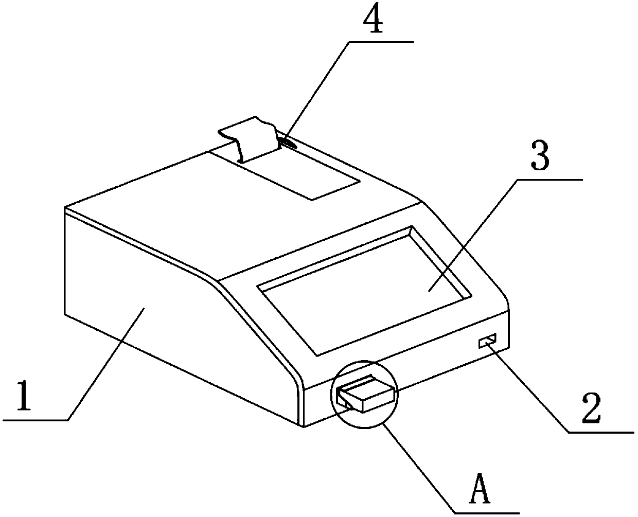
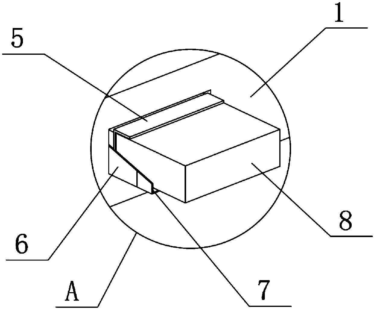
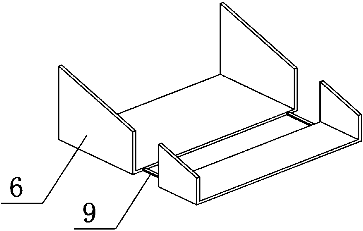
[0023] see Figure 1 to Figure 4 , the present invention provides a technical solution: a system for detecting the movement speed of immune cells, comprising an instrument body 1, an operation panel 3 is arranged on the surface of the instrument body 1, a detection port is opened at the bottom of the operation panel 3, and the outer side of the detection port is A C-shaped limiting plate 6 is fixed on the edge, and the inner surface of the C-shaped limiting plate 6 is at the same level as the bottom end surface of the detection port. The top of the C-shaped limiting plate 6 is connected to the limiting top plate 5, and the bottom of the limiting top plate 5 The end surface is at the same level as the top surface of the detection port, and a test paper card 8 is inserted into the detection port, the bottom of the test paper card 8 is attached to the inner surface of the C-shaped limit plate 6, and the top of the test paper card 8 is in contact with the limit top plate. The bott...

Embodiment 2

[0026] see Figure 1 to Figure 6 , the present invention provides a technical solution: a system for detecting the movement speed of immune cells, comprising an instrument body 1, an operation panel 3 is arranged on the surface of the instrument body 1, a detection port is opened at the bottom of the operation panel 3, and the outer side of the detection port is A C-shaped limiting plate 6 is fixed on the edge, and the inner surface of the C-shaped limiting plate 6 is at the same level as the bottom end surface of the detection port. The top of the C-shaped limiting plate 6 is connected to the limiting top plate 5, and the bottom of the limiting top plate 5 The end surface is at the same level as the top surface of the detection port, and a test paper card 8 is inserted into the detection port, the bottom of the test paper card 8 is attached to the inner surface of the C-shaped limit plate 6, and the top of the test paper card 8 is in contact with the limit top plate. The bott...


PUM


Abstract

The invention discloses an immune cell movement speed detection system. The system comprises an instrument body, an operation screen is arranged on the surface of the instrument body, a detection opening is formed in the bottom end of the operation screen, a C-shaped limiting plate is fixed to the edge of the outer side of the detection opening, the surface of the inner side of the C-shaped limiting plate and the bottom end face of the detection opening are located on the same horizontal plane, the top end of the C-shaped limiting plate is connected with a limiting top plate, and the bottom end face of the limiting top plate and the top end face of the detection opening are located on the same horizontal plane. As the limiting top plate and the C-shaped limiting plate are designed, when the test paper card is inserted into the instrument body, the test paper card can be effectively limited and fixed, the phenomenon of deviated insertion is avoided, stable operation is effectively guaranteed, meanwhile, the length of the C-shaped limiting plate can be increased or decreased through the designed adjusting column and the designed adjusting supporting plate according to actual operation, and the practicability is improved.

Description

technical field [0001] The invention belongs to the technical field of biology and microorganism analysis, and in particular relates to a detection system for immune cell movement speed. Background technique [0002] Immune cells refer to cells that participate in or are related to immune responses. In order to conduct in-depth research, it is generally necessary to detect the activity of immune cells through specific equipment. [0003] There are still some deficiencies in the existing detection system in use: when the existing detection device is in use, when the test paper card is inserted, because the socket has no device that can limit and fix it, it is easy to insert the test paper card to the wrong side, resulting in The side leakage of the test sample placed inside the test strip not only affects the work progress, but also has a certain impact on the working environment. There are certain limitations in use and there is room for improvement. Utility model content ...

Claims


Application Information

Patent Timeline
Patent Type & Authority Applications(China)
IPC IPC(8): G01N15/10
CPCG01N15/10G01N2015/1006G01N2015/1075
Inventor 肖光文
Owner JIAYING UNIV
Why Eureka
Try Eureka