Multiphase flow multiphase visual corrosion test device and method

A corrosion test, multi-phase technology, applied in the direction of measuring devices, weather resistance/light resistance/corrosion resistance, instruments, etc., can solve the problem of difficult observation of liquid deposition and sulfur particle precipitation in the pipe, change of flow field in the pipe, influence of fluid flow, etc. question

Active Publication Date: 2020-06-05
SOUTHWEST PETROLEUM UNIV
View PDF16 Cites 5 Cited by
  • Summary
  • Abstract
  • Description
  • Claims
  • Application Information

AI Technical Summary

Problems solved by technology

When the multiphase flow corrosive medium flows in the pipeline, it will have a fluid scouring effect on the wall surface. The different flow rates, flow rates and flow patterns of each phase have obvious differences in the scouring effect on the pipe wall, thus destroying the integrity of the corrosion inhibitor film. There is also a significant difference
[0005] Invention patent CN107764727 discloses a rotatable corrosion coupon device, which generates vortex flow through the rotating wheel, and designs a pre-stretched π-shaped transmission rod to realize the tight connection of each transmission part and π-shaped corrosion coupon, changing the corrosion resistance of the corrosion coupon. The curved section improves the bending resistance of the coupons and avoids the bending and yielding phenomenon of the corrosion coupons due to the impact of the air flow; the invention patent CN105699279 discloses a high-pressure metal pipeline non-stop corrosion coupon monitoring device. The completed vertical piston rod is moved up to the apex, and then the horizontal piston rod of the horizontal hydraulic cylinder assembly is moved to the leftmost end, so that the ball valve device blocks the lower part of the vertical hole of the body, and the interface of the body is completely sealed and isolated from the middle of the vertical hole of the body. Remove the vertical liquid cylinder assembly and the corrosion coupon, and indirectly monitor the corrosion of the pipeline by observing the

Method used


Image

  • Multiphase flow multiphase visual corrosion test device and method
  • Multiphase flow multiphase visual corrosion test device and method
  • Multiphase flow multiphase visual corrosion test device and method

Examples


Embodiment Construction

[0047] In order to have a clear understanding of the technical features, purposes and effects of the present invention, the specific implementation of the present invention will now be described with reference to the accompanying drawings.

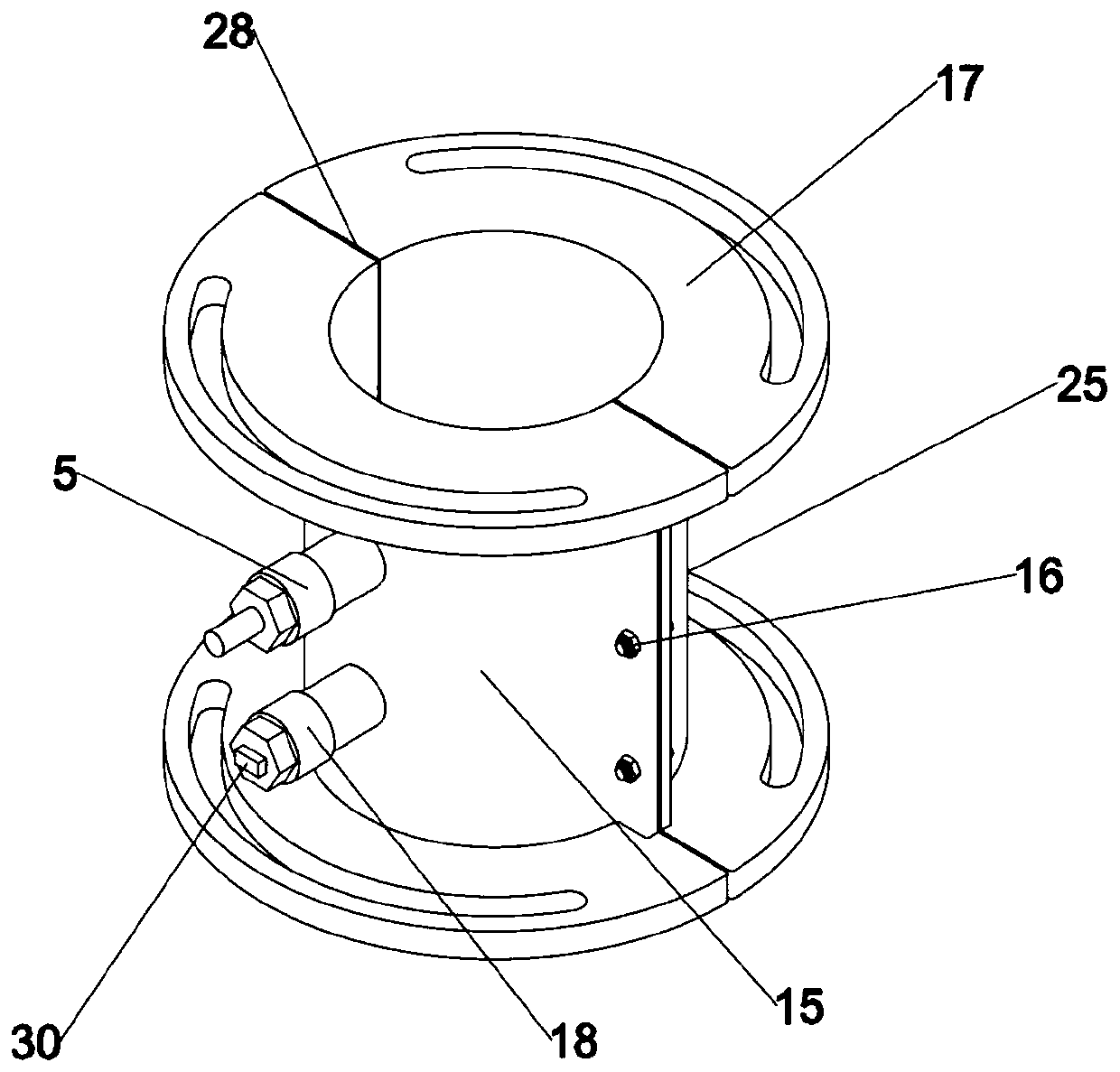
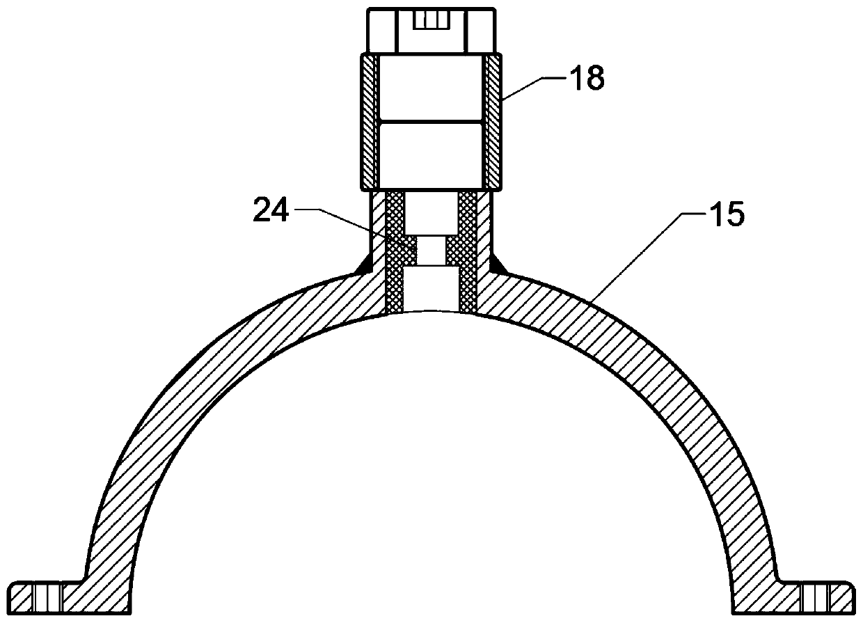
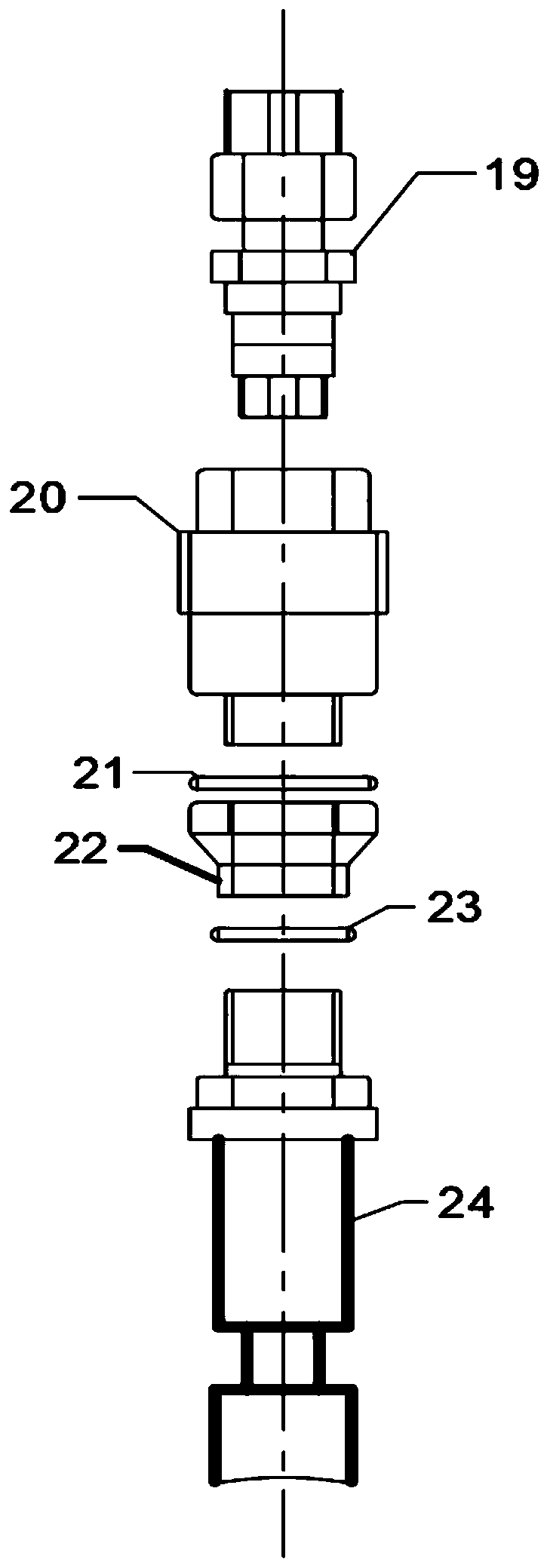
[0048] A multiphase flow multiphase visual corrosion test device, such as figure 1 As shown, it includes an open flange 17, screws 16, a resistance corrosion monitoring probe 5, a flat-head disc type hanging piece 30, a connecting sleeve 18, a corrosion monitoring unit 15, a visualization unit 25, a corrosion monitoring unit 15 and a visualization unit 25 It is connected by 6 screws 16, and a sealing gasket 28 is added in the middle. The upper and lower plates of the open flange 17 are provided with openings in the range of 30 degrees to 150 degrees. The openings are connected with ordinary flanges of pipelines. The corrosion monitoring phase area 4 is The opening of the installation flange in the range of 30° to 150° can place the resista...


PUM


Abstract

The invention discloses a multiphase flow multiphase visual corrosion test device and method, and belongs to the technical field of gas transmission pipeline and equipment corrosion monitoring. The device is mainly composed of a corrosion inhibitor filling unit, a corrosion monitoring phase area, a high-speed camera, a flow pattern control unit, a flow pattern recognition unit and the like. By utilizing the device and the method, the corrosion rate monitoring and corrosion inhibitor film integrity damage evaluation can be carried out by changing the flow rate and the flow rate of each phase ofa multiphase flow corrosion medium. The method comprises: firstly, the flow pattern control unit changing the flow and flow velocity of each phase of a corrosive medium; obtaining a flow pattern to be monitored; the flow pattern recognition unit and the high-speed camera respectively indirectly measuring and directly recognizing the flow pattern of the corrosive medium, then realizing multi-phasecorrosion monitoring through the change of a plurality of mounting angles of the corrosion monitoring phase region, and the corrosion monitoring phase region being provided with the semitransparent visualization unit, so that the condition of the corrosive medium in the pipe can be observed.

Description

technical field [0001] The invention relates to a multiphase flow multiphase visualized corrosion test device and method, belonging to the technical field of corrosion monitoring of oil and gas gathering and transportation pipelines and equipment. [0002] technical background [0003] At present, my country's sulfur gas reservoirs are facing a relatively serious problem in the development process, that is, corrosion. Corrosion is a phenomenon in which metal materials are destroyed by chemical or electrochemical reactions with the surrounding environment. Corrosion problems are almost common in all walks of life. This problem exists in all industries, but it is particularly prominent in petroleum refining and chemical enterprises. Whether it is in the production oil and gas fields or the oil and gas fields that are being explored and developed, the maintenance of oil and gas pipelines will consume a lot of manpower, material resources, and financial resources. Therefore, effect...

Claims


Application Information

Patent Timeline
IPC IPC(8): G01N17/00
CPCG01N17/006
Inventor 曾德智张思松杨志喻智明戚亚东于晓雨杨建起张新
Owner SOUTHWEST PETROLEUM UNIV
Why Eureka
Try Eureka