
Low-power-consumption band-gap reference circuit

A reference circuit, low-power technology, applied in the direction of adjusting electrical variables, control/regulating systems, instruments, etc., can solve problems such as current consumption, inability to meet low power consumption, and achieve the effect of reducing current consumption

Pending Publication Date: 2020-06-05
INNER MONGOLIA XIANHONG SCI
View PDF0 Cites 3 Cited by
  • Summary
  • Abstract
  • Description
  • Claims
  • Application Information

AI Technical Summary

Problems solved by technology

Although this structure is widely used in various circuit structures, due to the stability and bandwidth requirements of the operational amplifier itself, it needs to consume a certain amount of current, which cannot meet the requirements of low power consumption.

Method used


Image

  • Low-power-consumption band-gap reference circuit
  • Low-power-consumption band-gap reference circuit
  • Low-power-consumption band-gap reference circuit

Examples


Embodiment Construction

[0017] It should be understood that the specific embodiments described here are only used to explain the present invention, not to limit the present invention.

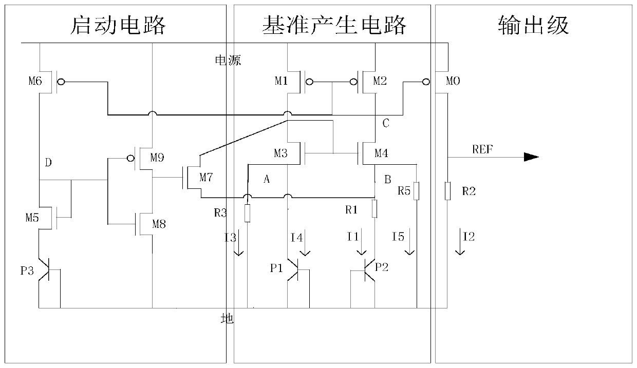
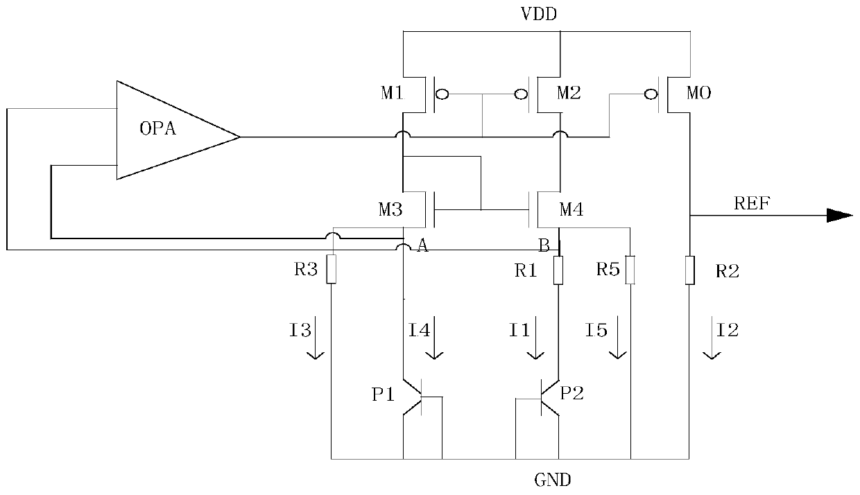
[0018] Please refer to figure 2 and image 3 , the present invention proposes a low power consumption bandgap reference circuit, wherein, figure 2 It is a schematic diagram of the circuit structure of a preferred embodiment of the low power consumption bandgap reference circuit of the present invention; image 3 It is a schematic diagram of the circuit structure of the reference generation circuit in the preferred embodiment of the low power consumption bandgap reference circuit of the present invention.

[0019] Such as figure 2 and image 3 As shown, in this embodiment, the low power consumption bandgap reference circuit includes a start-up circuit, a reference generation circuit, and an output pole, wherein the start-up circuit, the reference generation circuit, and the output pole are connected in sequence....


PUM


Abstract

The invention discloses a low-power-consumption band-gap reference circuit, and the circuit comprises a starting circuit, a reference generating circuit and an output electrode, wherein the starting circuit, the reference generating circuit and the output electrode are connected in sequence. According to the invention, the band-gap reference circuit solves the technical problem that a band-gap reference circuit in the prior art needs to consume certain current and cannot meet the requirement of low power consumption due to the requirements of stability and bandwidth of an operational amplifier, and the current consumption of a power supply management circuit is reduced.

Description

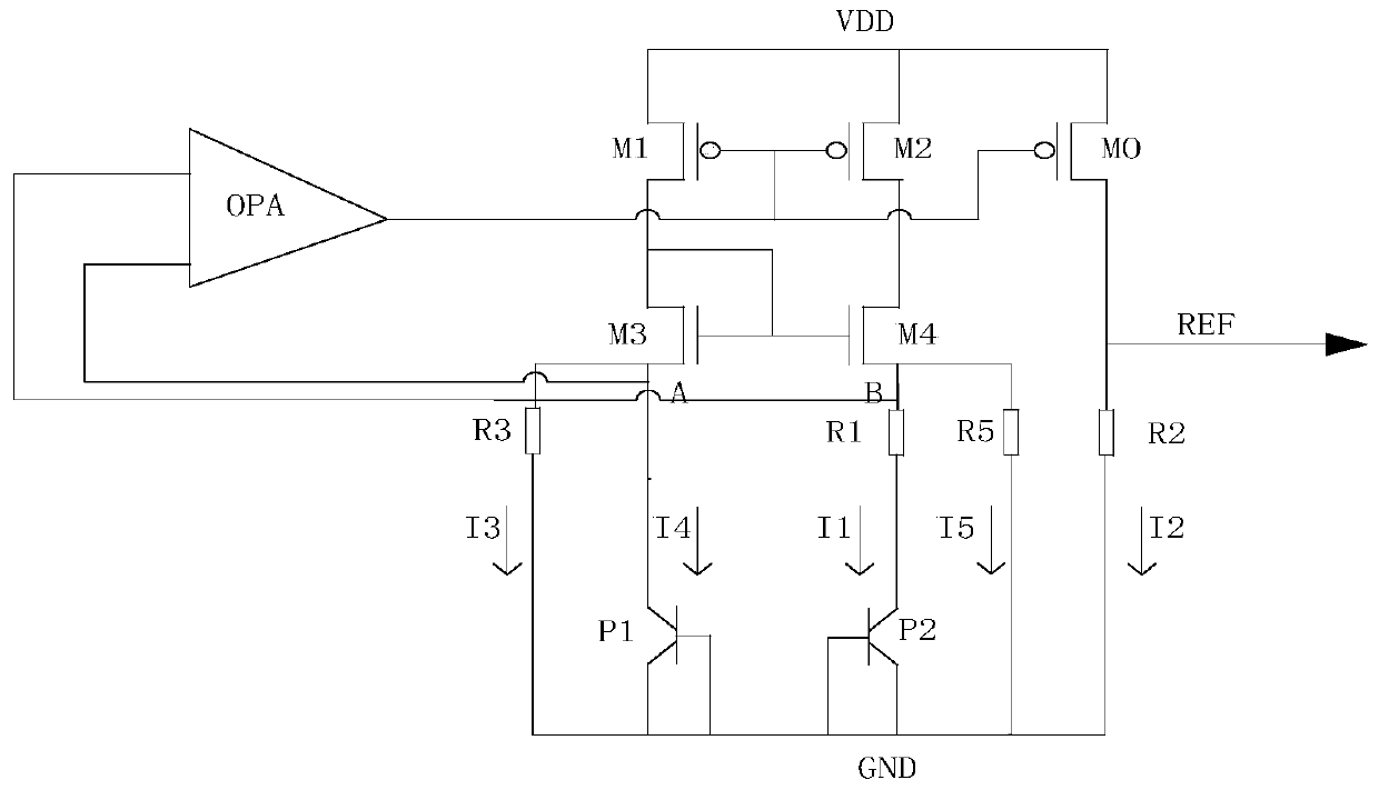
technical field [0001] The invention relates to the technical field of bandgap reference circuits, in particular to a novel low-power consumption bandgap reference circuit. Background technique [0002] In the field working environment, it is usually necessary to collect weak charges and charge related circuit modules, so as to ensure that the circuit can work stably for a long time. Its power management circuit has extremely strict requirements on power consumption, and its operating current needs to work below tens of nanoamperes. [0003] Such as figure 1 as shown, figure 1 It is a bandgap reference circuit in the prior art. The PMOS transistor M1 and the PMOS transistor M2 of the circuit form a current mirror circuit, and its bias is determined by the output of the op amp OPA. The input of the op amp is taken from the voltage points A and B. Use the feedback function of OPA to ensure that points A and B are the same, so as to ensure the normal operation of the bandgap...

Claims


Application Information

Patent Timeline
Patent Type & Authority Applications(China)
IPC IPC(8): G05F1/56
CPCG05F1/56
Inventor 黄志勇
Owner INNER MONGOLIA XIANHONG SCI
Learn More